
Securing industrial control systems and OT environments from remote attacks is more critical than ever, especially with vulnerabilities like CVE-2017-14469 and now CVE-2021-22659 that target Rockwell Automation’s widely used Micrologix 1400 Controller. Students from the OPSWAT Fellowship Program tested this vulnerability in a controlled environment, highlighting the need for security.
In this blog, we explore how the students demonstrated how attackers could exploit the vulnerability to cause systems to crash and how the lack of proper input validation could be leveraged to disrupt PLC operations.
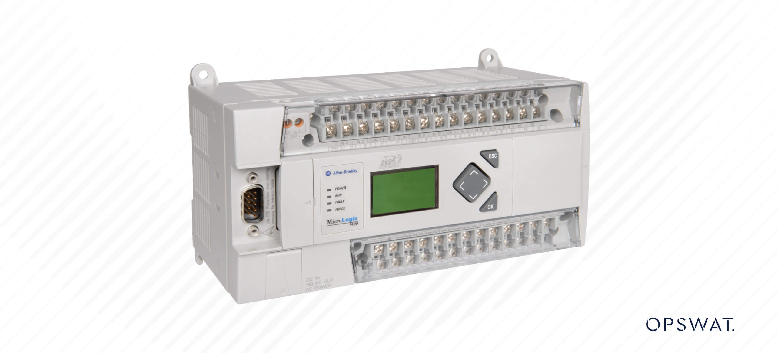
What is a PLC? Rockwell Automation Micrologix 1400 Explained
A PLC (Programmable Logic Controller) is an industrial computer designed to automate processes by controlling machinery and other industrial operations. It works in harsh environments and is programmed to perform specific tasks based on sensor input. Rockwell Automation's MicroLogix 1400 Controller is a compact and modular PLC commonly used in small to medium-sized applications. Known for its cost-effectiveness and flexibility, it supports various communication protocols and offers digital and analog I/O options for interfacing with devices.
Programming is typically done using Rockwell Automation's software through ladder logic, allowing users to create control sequences. The MicroLogix 1400 is versatile, suitable for tasks such as machine control and process automation. Its modularity allows users to expand and customize the system based on specific application requirements.
Introduction to CVE-2021-22659
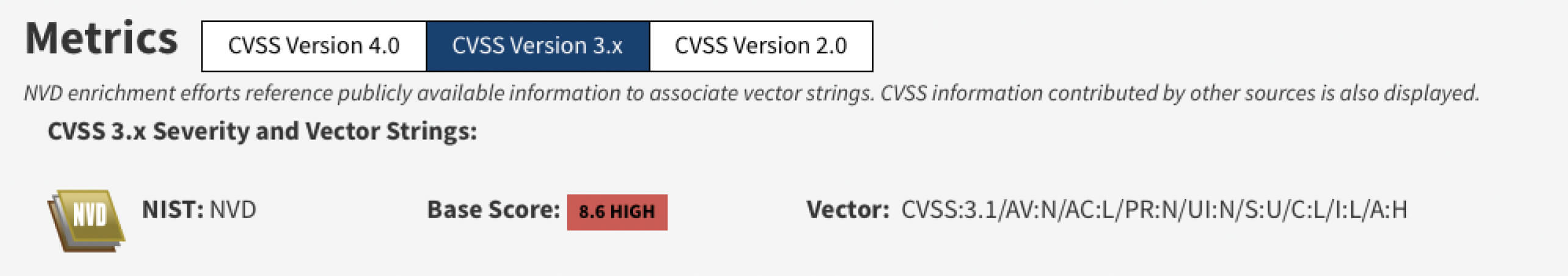
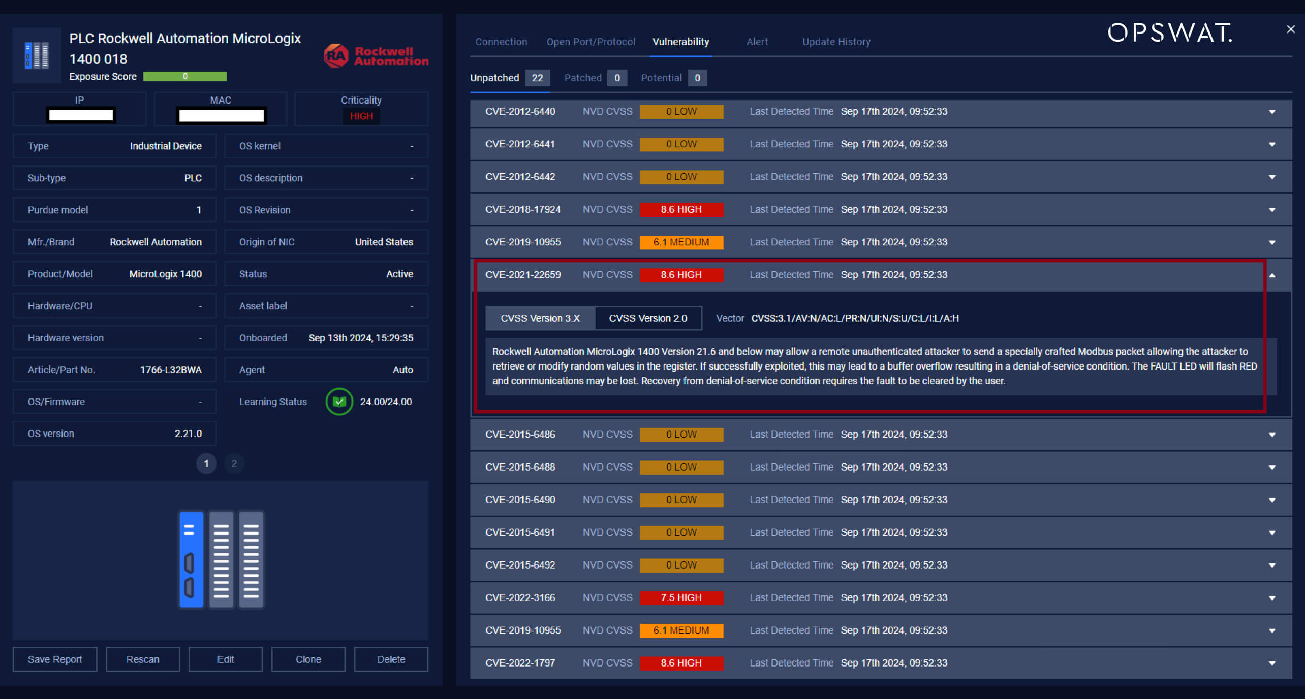
In January 2021, Rockwell Automation received a report from Parul Sindhwad and Dr. Faruk Kazi of the COE-CNDS at Veermata Jijabai Technological Institute (VJTI), India, regarding a vulnerability in the MicroLogix™ 1400 controller. They identified a security flaw in version 21.6 and earlier that allows a remote unauthenticated attacker to send a specially crafted Modbus packet, enabling the attacker to retrieve or modify random values in the register. If successfully exploited, this could lead to a buffer overflow, resulting in a denial-of-service condition. The FAULT LED will flash RED and communications may be lost. Recovery from denial-of-service condition requires the fault to be cleared by the user.
NVD evaluated this security vulnerability as High severity.
Attacking Phases
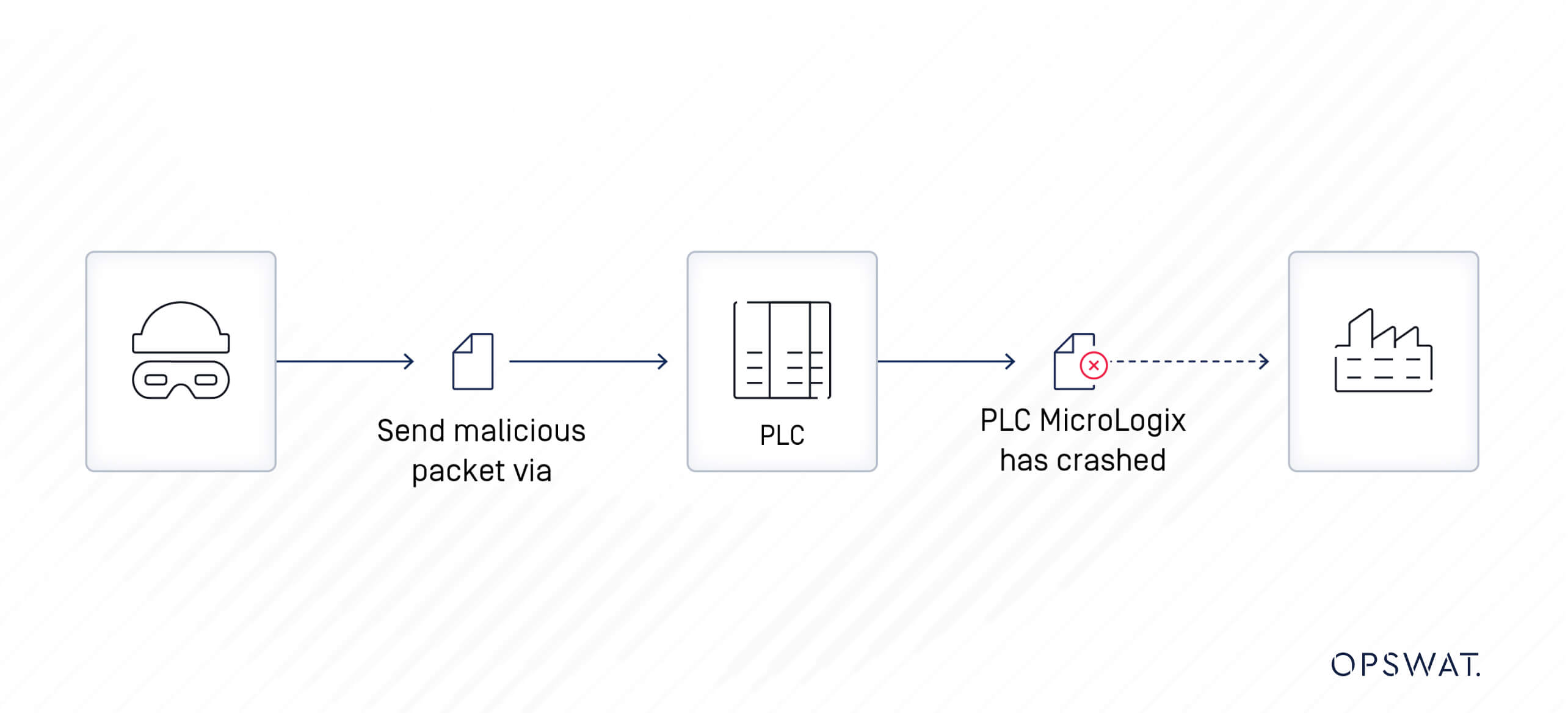
A remote, unauthenticated attacker with network access to the vulnerable MicroLogix 1400 PLC could send a specially crafted packet to modify the values in the register. This could potentially cause a denial-of-service condition for the device, resulting in system corruption and downtime. Such an incident can significantly disrupt manufacturing operations and other business activities of the organization.
Modbus Protocol
Developed by Modicon in 1979, the Modbus protocol is a messaging structure designed to establish client-server communication between intelligent devices. Originally designed for use with Modicon's PLCs, it has since become a standard communication protocol for communication between industrial electronic devices.
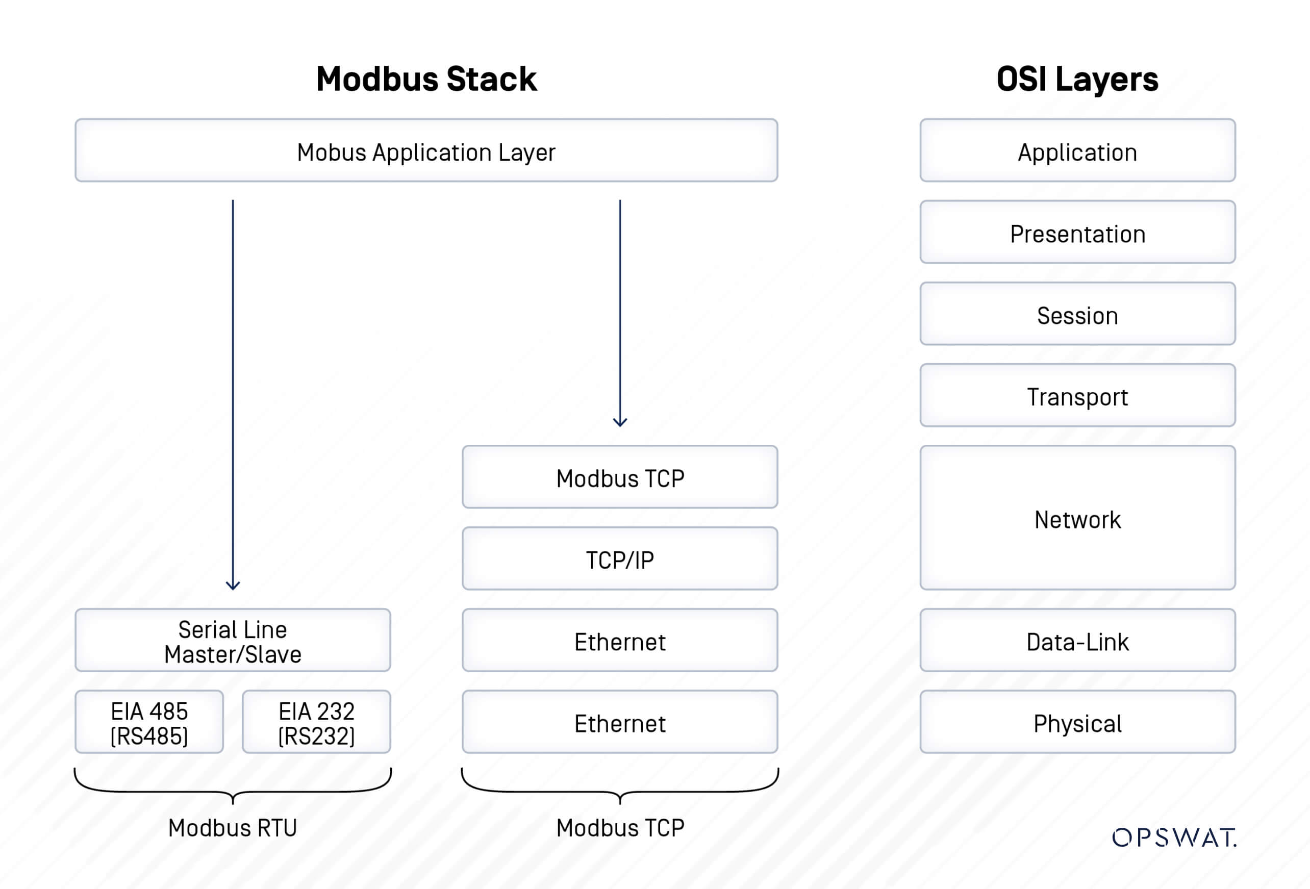
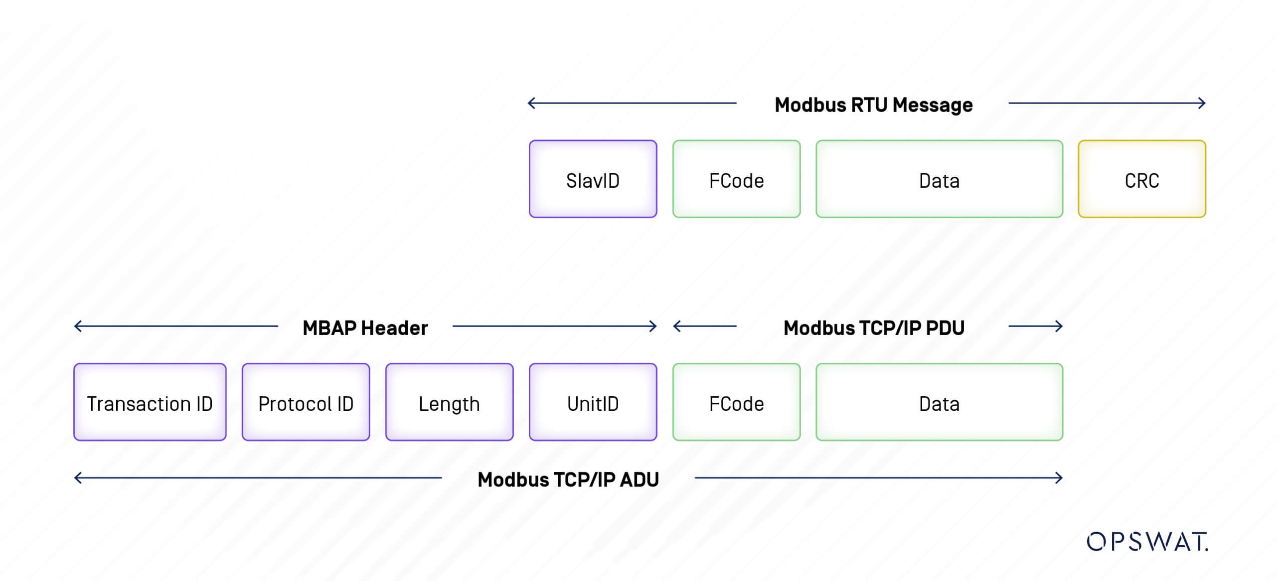
There are Modbus protocols for Ethernet (Modbus TCP) and serial lines (Modbus RTU and Modbus ASCII). Modbus RTU (Remote Terminal Unit) directly transmits data in binary form through serial communication, and Modbus TCP (Transmission Control Protocol) embeds Modbus protocol data into TCP packets for transmission over TCP/IP networks.
Modbus Message Structure
Modbus is a request-response protocol wherein the client transmits a request to a Modbus device, and the device subsequently provides a response.
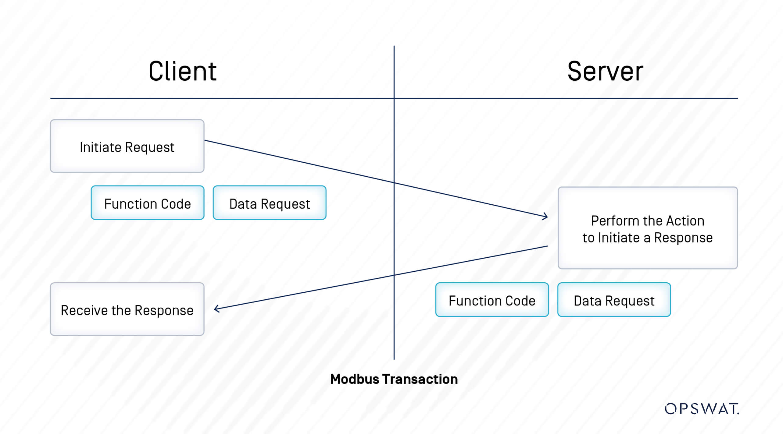
A Modbus message sent from a primary to a secondary contains the address of the secondary, the “command” (e.g. “read register” or “write register”), the data, and a check sum (LRC or CRC).
Data addresses are used in Modbus query messages when reading or modifying data. Modbus defines four Data Type: Coil, Input Status, Input Register and Holding Register. Two of them store on-off (1-bit) values called Coils and Discrete Inputs, and two store numerical values as 16-bit words called Registers. Each is either read-only or read/write.
| Data Type | Access | Description |
| Coil | Read-write | Single bit outputs. |
| Discrete Input | Read-only | Single bit inputs. |
| Input Register | Read-only | 16-bit input registers. |
| Holding Register | Read-write | 16-bit output registers. |
There are three categories of Modbus function codes:
- Public Function Codes – From 1 to 127 except for user-defined codes.
- User-Defined Function Codes – in two ranges from 65 to 72 and from 100 to 110.
- Reserved Function Codes – Used by some companies for legacy products and not available for public use.
| Function type | Function name | Function code | ||
| Data Access | Bit access | Physical Discrete Inputs | Read Discrete Inputs | 2 |
| Internal Bits or Physical Coils | Read Coils Write Single Coil Write Multiple Coils | 1 5 15 | ||
| 16-bit access | Physical Input Registers | Read Input Registers | 4 | |
| Internal Registers or Physical Output Registers | Read Multiple Holding Registers Write Single Holding Register Write Multiple Holding Registers Read/Write Multiple Registers Mask Write Register Read FIFO Queue | 3 6 16 23 22 24 | ||
| File Record Access | Read File Record Write File Record | 20 21 | ||
| Diagnostics | Read Exception Status Diagnostic Get Com Event Counter Get Com Event Log Report Slave ID Read Device Identification | 7 8 11 12 17 43 | ||
| Other | Encapsulated Interface Transport | 43 | ||
| Function type: Data Access Sub-type: Bit access Category: Physical Discrete Inputs Function name: Read Discrete Inputs Function code: 2 |
| Function type: Data Access Sub-type: Bit access Category: Internal Bits or Physical Coils Function name: Read Coils Function code: 1 |
| Function type: Data Access Sub-type: Bit access Category: Internal Bits or Physical Coils Function name: Write Single Coil Function code: 5 |
| Function type: Data Access Sub-type: Bit access Category: Internal Bits or Physical Coils Function name: Write Multiple Coils Function code: 15 |
| Function type: Data Access Sub-type: 16-bit access Category: Physical Input Registers Function name: Read Input Registers Function code: 4 |
| Function type: Data Access Sub-type: 16-bit access Category: Internal Registers or Physical Output Registers Function name: Read Multiple Holding Registers Function code: 3 |
| Function type: Data Access Sub-type: 16-bit access Category: Internal Registers or Physical Output Registers Function name: Write Single Holding Register Function code: 6 |
| Function type: Data Access Sub-type: 16-bit access Category: Internal Registers or Physical Output Registers Function name: Write Multiple Holding Registers Function code: 16 |
| Function type: Data Access Sub-type: 16-bit access Category: Internal Registers or Physical Output Registers Function name: Read/Write Multiple Registers Function code: 23 |
| Function type: Data Access Sub-type: 16-bit access Category: Internal Registers or Physical Output Registers Function name: Mask Write Register Function code: 22 |
| Function type: Data Access Sub-type: 16-bit access Category: Internal Registers or Physical Output Registers Function name: Read FIFO Queue Function code: 24 |
| Function type: Data Access Sub-type: File Record Access Function name: Read File Record Function code: 20 |
| Function type: Data Access Sub-type: File Record Access Function name: Write File Record Function code: 21 |
| Function type: Diagnostics Function name: Read Exception Status Function code: 7 |
| Function type: Diagnostics Function name: Diagnostic Function code: 8 |
| Function type: Diagnostics Function name: Get Com Event Counter Function code: 11 |
| Function type: Diagnostics Function name: Get Com Event Log Function code: 12 |
| Function type: Diagnostics Function name: Report Slave ID Function code: 17 |
| Function type: Diagnostics Function name: Read Device Identification Function code: 43 |
| Function type: Other Function name: Encapsulated Interface Transport Function code: 43 |
Exploitation
Vulnerability Analysis
Through analysis, our OPSWAT Graduate Fellows discovered that during Modbus TCP communication, the protocol lacks authentication and encryption for transmitted packets. Additionally, input validation in the MicroLogix 1400 PLC is not implemented properly. Consequently, a remote attacker can analyze the Modbus TCP packet via packet sniffing and send any request to the PLC without authentication via the Modbus TCP protocol. Due to the MicroLogix 1400 PLC device's lack of input validation, a remote authenticated attacker could send a large number of packets with random values, potentially causing the PLC to crash.
Register Overwriting
Initially, we attempted to capture Modbus TCP packets used for reading or writing registers on the PLC. To accomplish this, we examined packets generated by an application named Modbus Poll, which facilitates the reading and writing of registers on the MicroLogix 1400 PLC.
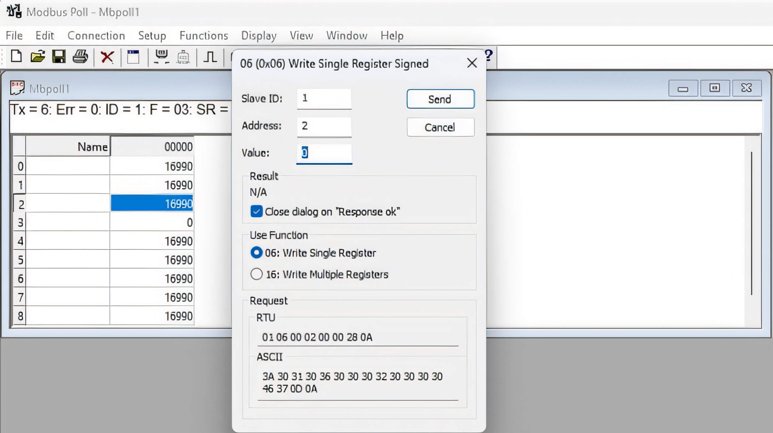
By using Wireshark to capture all packets from the network interface, we could identify the Modbus TCP packet for writing a single register:
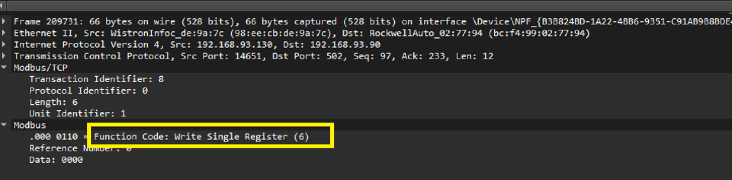
Based on the structure of the sniffed packets, we developed a simple Python script to send TCP packets requesting the writing of a register on the target PLC. In this scenario, the IP address of the PLC is 192.168.93.89.
The register of the PLC was changed after receiving our malicious unauthenticated packet.
In Micro Logix 1400, most math instructions use three parameters: Source A, Source B and Destination
The values for Source A and Source B can come from two 16-bit registers named N13:3 and N13:4. Furthermore, the values in these 16-bit registers, such as N13:3 and N13:4, are constrained within the range of -32,768 to +32,767. If the values of N13:3 and N13:4 are large, the result of the match instruction may exceed the data type's maximum range, potentially causing the PLC to crash. Consequently, to induce a crash in the PLC, it is necessary to write large random values to all registers, including N13:3 and N13:4. To achieve this, we modified our Python script as follows:
Simulate the Attack
To simulate a real-world attack, our OPSWAT Graduate Fellows attempted to induce a crash in the MicroLogix 1400 PLC located in OPSWAT CIP Labs, under the assumption that both the attacker and the PLC are on the same network and able to communicate with each other.
In the normal operational state of the MicroLogix 1400 PLC at OPSWAT Labs, with the PLC in REMOTE RUN mode, all register values are valid and fall within the designated range for their data types, indicating that the user program is functioning correctly.
Upon execution of our Python script, numerous Modbus TCP packets will be sent to the PLC, requesting the writing of large random values to all registers without authentication:
After receiving these malicious packet requests, the values of all registers, including N13:3 and N13:4, are set to 16,990. The result of the ADD operation on the N13:3 and N13:4 registers exceed the valid range of a 16-bit register. This issue causes an integer overflow, leading to a fault and interrupting the operation of the PLC, as indicated by the FAULTED state.
Our OPSWAT Graduate Fellows have successfully crashed the MicroLogix 1400 PLC by exploiting CVE-2021-22659.
Remediation
In the face of vulnerabilities like CVE-2021-22659, comprehensive remediation is crucial for protecting OT and cyber-physical systems. Given below are some of the key strategies that can be employed to prevent the spread of attacks:
- Detecting known CVEs: Regularly scanning networks for vulnerabilities like CVE-2021-22659.
- Monitoring for anomalous behaviors: Flagging unusual increases in frequency in communication to the Micrologix 1400 PLC, which could suggest an ongoing attack of unauthorized data transfer.
- Identifying new device connections: The system should detect when a new device connects to the PLC.
- Network segmentation: Isolating affected devices can help prevent the lateral spread of attacks, thus minimizing impact.
OPSWAT’s MetaDefender OT Security addresses these needs by detecting CVEs, continuously monitoring the network for unusual behaviors, and identifying unauthorized connections. Using AI, it learns normal traffic patterns, establishes baseline behavior, and implements policies to alert anomalies. This allows instant, informed responses to potential threats.
In the case of an attack exploiting CVE-2021-22659, MetaDefender OT Security integrates with the MetaDefender Industrial Firewall to block suspicious communications based on set rules. The firewall uses AI to learn regular traffic patterns and enforce policies to prevent unauthorized connections.
By combining these detection, alerting, and network segmentation capabilities, MetaDefender OT Security becomes the ideal defense mechanism for industrial environments, significantly reducing the risk and impact of cyberthreats in operational technology environments.
Explore how OPSWAT’s defense-in-depth cybersecurity platform can enhance and mature your posture. Talk to an expert today for a free demo.