The Modbus Connector enables transfer of Modbus data unidirectionally across the MetaDefender Optical Diode (hereinafter Optical Diode). The Modbus Connector is configured on the Optical Diode on both the BLUE and RED sides.
Configuring the Modbus Connector on Optical Diode BLUE creates a Modbus client on the BLUE side and a Modbus server on the RED side.
The Modbus client on Optical Diode BLUE collects data from customer-owned Modbus servers on the BLUE side and transfers data to the Modbus server, configured on Optical Diode RED. Customer-owned Modbus clients on the RED side connect to the Modbus server to collect the transferred data.
Optical Diode BLUE
A security dongle must be inserted in the BLUE and RED servers to change configuration.
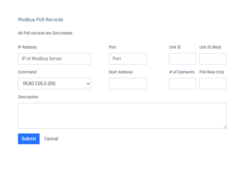
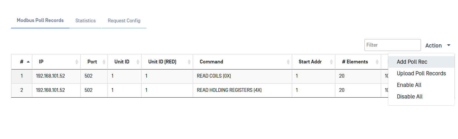
In the Modbus Connector, all Poll records are zero based.
Navigate to the Modbus menu item under the Connectors menu, In the Action menu, select Add Poll Rec.
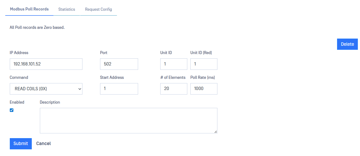
Type values in the following boxes:
IP Address: IP address of the customer-owned Modbus server that the Optical Diode Modbus client will collect data from.
Port: Modbus port on the Modbus server.
Enter the following Modbus-specific information to configure Modbus Poll records:
Unit ID: This field is used for intra-system routing purpose. It is typically used to communicate to a MODBUS+ or a MODBUS serial line slave through a gateway between an Ethernet TCP-IP network and a MODBUS serial line. This field is set by the MODBUS Client in the request and must be returned with the same value in the response by the server. The Unit Identifier is used to communicate via devices such as bridges, routers and gateways that use a single IP address to support multiple independent MODBUS end units.
Unit ID (Red): Same as before but for the RED side
Start Address: Start address for the Poll record
# of Elements: Number of elements the poll will check
Poll rate (in milliseconds)
Command (select from dropdown)
Click on Submit button to save the changes.
When configuring a Poll Record, it is not possible to configure two or more Poll records, checking against the same register. Over lapping poll records will be rejected.
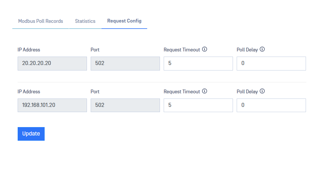
Configure Response Timeout Value
Navigate to the Request Config tab
Type values in the following boxes:
Request Timeout: a timeout in seconds for every request per IP and Port. Default value is 5. Valid range 5 - 60.
Poll Delay: Poll delay in milliseconds per IP and Port. A value greater than 0 will overwrite the value of "Poll Rate" of every poll record with the same IP and Port. Leave 0 to honor each "Poll Rate" value in Modbus poll records. Default 0 (or 1,000 for non-0 value), valid range 10 - 30,000.
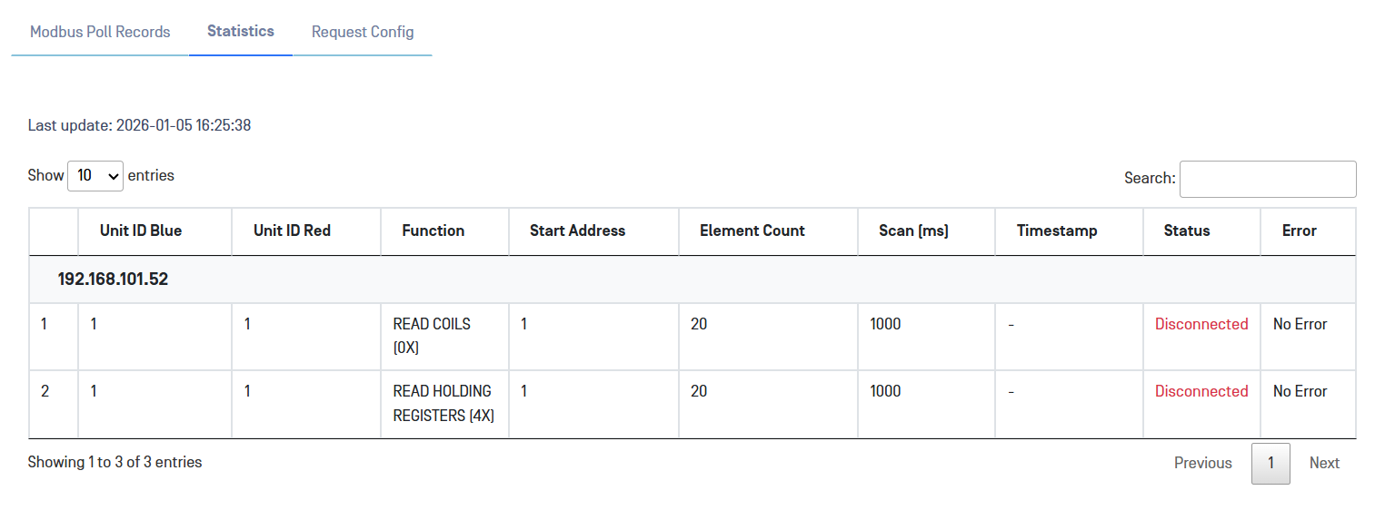
Statistics (BLUE)
View Modbus BLUE statistics by clicking on the Statistics tab:
Optical Diode RED
A security dongle must be inserted in the RED server to change configuration.
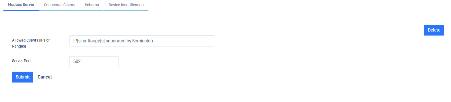
Navigate to the Modbus menu item under the Connectors menu, In the Action menu on the far right hand side, select Add Poll Rec.
Allowed IPs: IP addresses of the customer-owned Modbus clients in the RED zone that will connect to the OPSWAT Modbus server and monitor the Modbus data sent across the Optical Diode. You can enter multiple addresses, separated by a semicolon.
Port: Modbus port on the OPSWAT Modbus client
Click on Submit to save the changes.
Edit/Delete Poll Records
Navigate to the Modbus menu item under the Connectors menu.
In the Action menu, select Add Poll Rec.
Click on Edit or Delete menu and edit the fields.
Click Submit to save the changes.
Click on Delete or Edit the record. A confirmation pane displays. Click Yes to confirm your action.
Click the Delete button to delete the record. A confirmation pane displays. Click Yes to confirm your action.