1 Preface
The Management Console Guide provides information for installing and configuring the Management Console hardware and software in your environment.
Who should read this
This guide is for system administrators responsible for the security of an organization’s network.
Before you start
Before you install any appliance, OPSWAT recommends that you do a cybersecurity assessment and analysis with your organization to calculate the necessary equipment and where to install it. Speak to your sales person for full information.
Support
Contact OPSWAT support using:
- Email: support@opswat.com
- Phone: +1.844.200.
2 Introduction
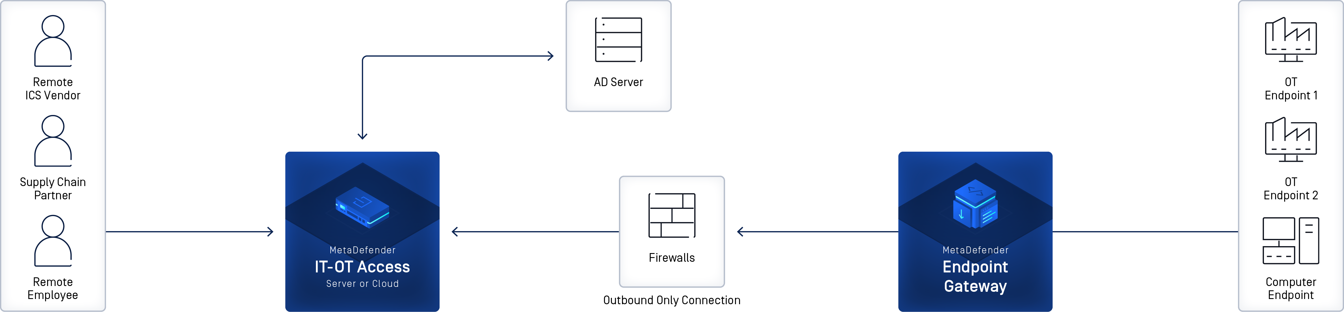
Secure OT Access (MetaDefender Endpoint Secure OT Access) is a remote access tool that provides a platform for publishing and monitoring connections between Remote Users and industrial assets. The software contains built-in tools for security and manageability.
Secure OT Access features include:
- The ability to deploy in the Cloud or onsite
- The Cloud deployment has no required hardware and can be set up in one day or less.
- The onsite Management Console is easy to install. This deployment can also be set up in one day.
- Integrates with your Active Directory server for user and Security Group authorization
- Enables Policy Enforcement per user and per session
- Outbound-only connection from endpoint gateway to Secure OT Access Cloud or Management Console, with no inbound firewall exceptions required
- Inexpensive and flexible pricing model on annual or monthly subscription
- Cloud components are hosted on Amazon Web Services (AWS) for maximum reliability and performance.
Secure OT Access deployments
Secure OT Access has two possible deployments:
- Cloud: OPSWAT manages Secure OT Access configuration, including tasks such as uploading new software versions (personalities) and setting Management IPs.
- Onsite: The Management Console allows the customer to perform internal Secure OT Access configuration tasks. Traffic inspection and policy enforcement is performed in the onsite server, making it suitable for offline deployments with no internet access.
Except for the use of the Management Console, both deployments have essentially the same functionality. You will receive the equipment, software, etc. appropriate to your deployment.
Secure OT Access components
Secure OT Access components differ, depending on the deployment:
- Admin UI (onsite and Cloud): Configures and manages connections between the Remote User’s primary computer and their OT Endpoint Devices.
- Windows Client (onsite and Cloud): Connects the Remote User’s primary computer to the Cloud or to the Management Console and ultimately to their OT Endpoint Devices.
- Windows Service Client (onsite and Cloud): Windows system-level service that can be used as an alternative to the Windows Client. The service launches automatically when the computer boots and provides a persistent connection through Secure OT Access to the services assigned to the user.
- Management Console (onsite deployment only): Performs Secure OT Access internal configuration tasks through the Console UI.
Refer to the Installation and Administration Guide for information on installing and configuring the Admin UI, Windows Client, and Windows Service Client.
Order of Tasks
The Cloud and onsite deployments require different installation and configuration tasks.
Cloud deployment
1) Install and configure Windows Client or Windows Service Client on the Endpoint Gateway.
2) Install and configure Windows Client or Windows Service Client on the Remote User’s computer. If the Remote User connects to clientless services only, this step is not necessary.
3) Log into the Admin UI to configure the connections between the Remote Users and their associated assets.
Onsite deployment
1) Install the Management Console hardware and configure the Management Console software.
2) Install and configure Windows Client or Windows Service Client on the Endpoint Gateway.
3) Install and configure Windows Client or Windows Service Client on the Remote User’s computer. If the Remote User connects to clientless services only, this step is not necessary.
4) Log into the Admin UI to configure the connections between the Remote Users and their associated assets.
3 Install Management Console hardware
Comply with any earthquake bracing, ESD, cabling, and labeling or other requirements for your organization.
Prerequisites
Environmental requirements
| Parameter | Limits |
|---|---|
| Temperature | -10-35ºC Operating -40-65ºC Non-Operating |
| Humidity (RH) | 5 - 95% non-condensing Non-Operating 10 - 80% RH Operating |
Power requirements
| Item | Limits |
|---|---|
| Type / Watts | 250 Watts |
Hardware requirements
If any items you are supposed to receive are missing or damaged, contact Support.
You will receive a package from OPSWAT containing the following:
- Dell 1U server
- Mounting rail kit
- Power cable
In addition, you must have:
- Flathead screwdriver
- Ethernet cables
The installation location must provide:
- Access to the rear of the Management Console
- 1U rack space
- 250 Watts power in the rack where the nodes will be installed
Safety information
Obey these safety guidelines to ensure general safety:
- Keep the chassis area clear and dust-free before, during, and after you do the install.
- Do not put on loose clothing or jewelry that could catch in the chassis. Attach or remove your tie or scarf and roll up your sleeves.
- Put on safety glasses/goggles if you work in conditions that could be dangerous to your eyes.
- Do not do a step that can cause a risk to persons or makes the equipment dangerous.
- Switch off all power and disconnect the power cord before you install or remove a chassis or work near power supplies.
- Do not work without help in possibly dangerous conditions.
- Always measure the power circuit to make sure you have disconnected it.
Operating safety
- Electrical equipment makes heat. Keep the room at a permitted temperature range with more air circulation if necessary. Be sure that the room in which you operate your system has sufficient air circulation.
- Make sure that you close the chassis cover correctly. The chassis design lets cool air circulate correctly. An open chassis changes the air flow, which can stop the air flow or circulate the flow from internal components.
Electrostatic Discharge
Electrostatic Discharge (ESD) can damage equipment and impair electrical circuitry. ESD damage occurs when electronic components are incorrectly handled and can result in complete or intermittent failures. Obey ESD-prevention procedures when you remove and replace components to avoid these problems.
- Put on an ESD-preventive wrist strap, making sure that it makes good skin contact. If no wrist strap is available, you can make ground contact through touching the metal part of the chassis.
- Regularly check that the resistance value of the antistatic strap is between 1 and 10 megohms (Mohms).
Installation procedure
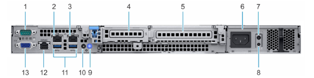
The following figure and table describe the Management Console ports.
| Port | Description | Connection |
|---|---|---|
| 1 | Serial port | N/A |
| 2 | NIC port (Gb1) | Connect to the management system. |
| 3 | NIC port (Gb2) | N/A |
| 4 | Half-height PCIe expansion card slot | N/A |
| 5 | Full-height PCIe expansion card slot | N/A |
| 6 | Power supply unit | Connect to the power on the rack. |
| 7 | PSU Built-in Self Test (BIST) LED | N/A |
| 8 | PSU Built-in Self Test (BIST) button | N/A |
| 9 | System identification button | N/A |
| 10 | System status indicator cable port (CMA) | N/A |
| 11 | USB 3.0 ports (2) | N/A |
| 12 | iDRAC dedicated NIC port | N/A |
| 13 | VGA port | N/A |
1) Install the Dell server in the rack with the mounting rails kit, following your local procedures.
2) Connect the NIC port (#2 on the graphic) to the management system, using the Ethernet cable.
3) Connect the power supply (#6 on the graphic) to the power on the rack.
4) Power up the Management Console.
4 Configure Management Console software
You must configure the Management Console software before you can access the Windows Client or Admin UI. Perform the procedures in this chapter, in order.
Prerequisites
Be sure you have the following information before you begin configuring the Management Console software:
- License file: Provided by OPSWAT
- Secure OT Access Windows Client software: Provided by OPSWAT
- Username and password for the Management Console UI: Default values provided by OPSWAT.
- Superadmin (user and password) for the Admin UI. Refer to the Installation and Administration Guide for information on configuring and using the Admin UI.
- Administrator access. Consult with your software administrator.
- Two internal IP addresses (Management IP and Service IP). Both addresses should be open on Port 443 for internal and external traffic. The Management IP address should also be open on Port 8443 for internal traffic.
- Two external IP addresses (IP to access the Admin UI and IP to enable connections into the permitted endpoints). Both addresses should be open on Port 443 for external and internal traffic.
- Port 443 should have open firewalls towards the Management Console.
- Port 8443 should have open interior firewalls towards the Management Console. These firewalls should be open only on machines that will be used to access the Management Console.
- NAT External IP to Internal IP
- Active Directory or LDAP server (optional). Needed to use an Active Directory to manage your users. You may need to open port 444 in your firewall as well.
- External DNS server (optional). Needed to use 2fa (two-factor authentication).
- SMTP server (optional). Needed to allow the system to send notifications via email.
- If you are configuring clientless services with the HTTPS protocol, you also need the following (refer to the Installation__and Administration Guide for more information):
- One top-level domain
- Two subdomains: one for the Console UI and one for the HTTPS clientless services
- Two specific certificates for the subdomains or one wildcard certificate that is valid for both subdomains
Configure the Management IP
You will use the Management IP address to connect to the Management Console interface (Console UI) via the Internet. Secure OT Access provides a default Management IP of 10.10.10.10. You can update this IP from the Console UI. However, before you can access the Console UI, you must add an IP address to your system to be able to access the 10.10.10.10 range.
The method used to add the IP address differs, depending on whether you are using a Linux or Windows system.
Add an IP to a Linux NIC
To add an IP to a Linux Network Interface Card (NIC), open a command line and enter the following command:
ip address add [ip]/[mask-digits] dev [nic]
- ip : Address in the default Management IP range. The range can be from 10.10.10.1 to 10.10.10.255
- mask-digits : Subnet mask. Refer to “Subnet mask chart” for more information.
- nic : Ethernet interface for the NIC.
For example:
ip address add 10.10.10.11/24 dev eth
Add an IP to a Windows NIC
Add one or more IP addresses to a single NIC in Windows 7, 8.1, or 10 as follows:
1) Open a command line and enter the ipconfig command to determine the IP address of your current machine. Make a note of this value.
2) Determine the Subnet Mask for this IP Address. Refer to “Subnet mask chart” for more information.
3) Open your Control Panel and select Network and Internet > Network Connections. Right-click the interface where you want to add the IP, or double-click the Ethernet or Wi-Fi connection.
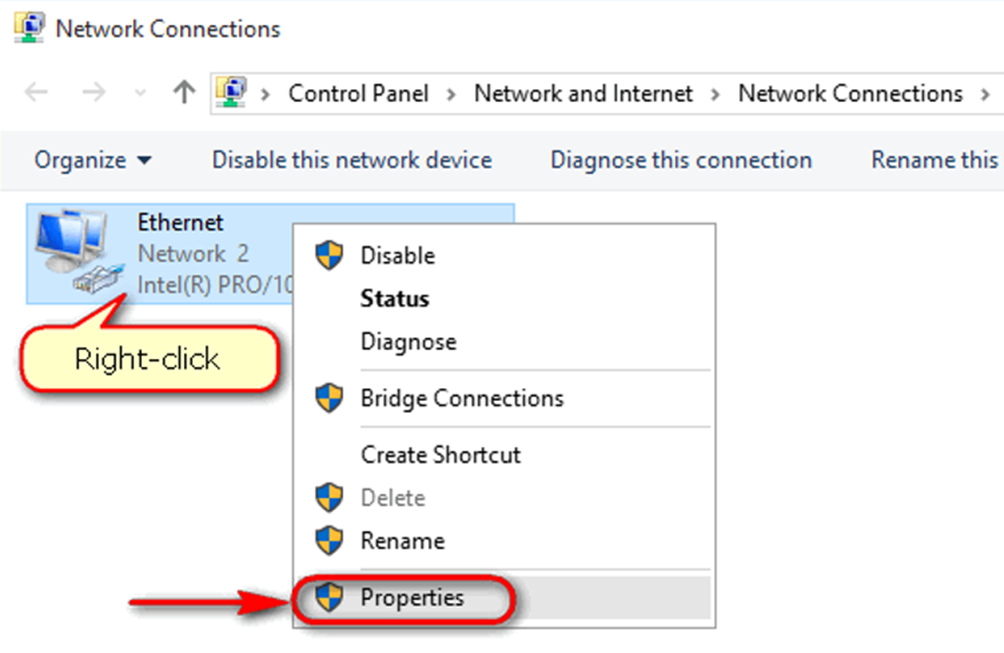
4) Click Properties. The Ethernet Status window displays.
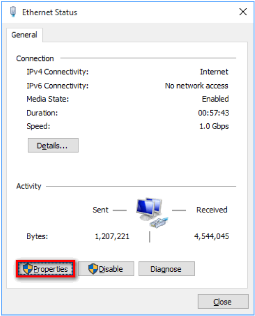
5) Click the Properties button. The Ethernet Properties window displays.
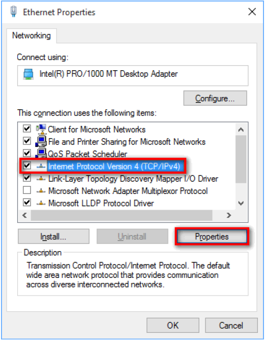
6) Select Internet Protocol Version 4 (TCIP/IPv4) and click the Properties button. The Internet Protocol Version 4 (TCP/IPv4) Properties window displays.
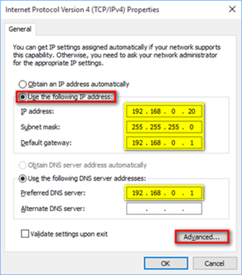
7) Click Use the following IP address.
8) Type the IP address , Subnet mask , and the IP addresses for the Default Gateway and Preferred DNS server. Use the values determined in Steps 1 and 2 for IP address and Subnet mask.
9) Click Advanced... The Advanced TCP/IP Settings window displays.
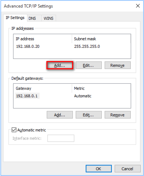
10) Click the Add button. The TCP/IP Address window displays.
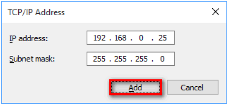
11) Type the IP address and Subnet mask of the address in the default Management IP range that you want to add to your system. The range can be from 10.10.10.1 to 10.10.10.255.
12) Click the Add button. You return to the Advanced TCP/IP Settings window.
13) Click the OK button until you return to the Ethernet Properties window.
14) Click the Close button.
Log on to the Management Console
To log on to the Console UI, open a browser window and enter an IP address for the web interface, followed by port # 8443. Enter the user name and password when prompted.
Note
- The first time you log on, use the default 10.10.10.10 IP address, followed by Port 8443. After you “Update the Management IP”, log on with the new IP address and Port 8443.
Upload the license
Before you start
- You will need appropriate privileges.
- Each onsite deployment needs a unique license: One license = One onsite deployment.
- To request an extension on evaluation licenses or new/renewal of production licenses, contact support@opswat.com
1) Log on to the Management Console.
2) The first time you log on, the End User License Agreement (EULA) opens. Read the agreement, click the box to verify you accept the terms in the agreement, and click the Submit button.
3) The License Upload page displays. The license files are supplied to you. Make sure you saved the new license to a location on the Secure OT Access network.
4) In the Local License File box, click Browse to navigate to the file. Select the file.
5) Click the Upload License button to start the upload. The Progress Bar shows when the upload completes.
6) Click and read the End User License Agreement (EULA) link. Click the check box to show you accept the terms. A green banner at the top of the page tells you the procedure succeeded. The License page opens with the new information.
7) The SSL/TLS credentials pane displays. Use this pane to update the SSL Certificate. Refer to “SSL/TLS Credentials” for more information. Click the Continue button to continue configuration.
Note
- You do not have to update the SSL certificate during the license upload. Use the “SSL/TLS Credentials” menu option to update the certificate at any time.
8) The Finalize Secure OT Access Config page displays. Create a superuser name and password. The user name default is “superadmin”. Type and confirm the password. Click the Submit button.
9) The Console dashboard displays.
After you upload the license for the first time, you can use the License option on the Configuration menu to update or delete the license. Refer to “License”.
Configure an L3 route
Use the L3 Routes menu option to manage target routes and gateways.
1) Open the Networking menu and click L3 Routes. The L3 Routes pane displays.
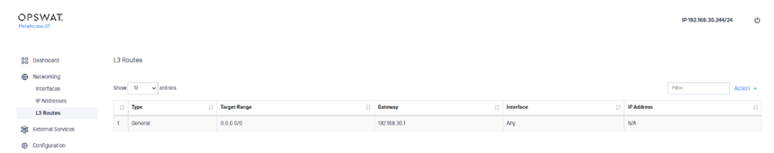
2) Open the Action menu and select Add L3 Route. An edit pane displays.
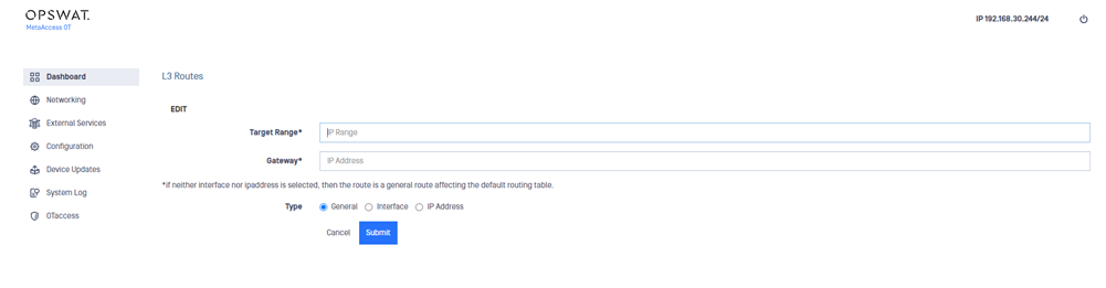
3) Enter the following information:
- Target Range : Destination IP address or range of addresses for the traffic
- Gateway : IP address for the gateway
- Type : Type of static route being added. Defaults to General but can be defined as Interface or IP Address.
4) Click the Submit button.
To edit or delete a route, double-click the route on the L3 Routes pane to open a detail pane for that route. Open the Action menu on the detail pane and select Edit or Delete , respectively.
Update the Management IP
Use the Console UI to change the Management IP from the default IP address of 10.10.10.10.
Notes
- The Management IP can be set on any interface.
- Moving the Management IP to another interface generally requires networking cable changes.
- After you update the Management IP, use the new address to log on to the Management Console. The 10.10.10.10 address will no longer work.
- The value set for the Management IP will automatically populate the Clientless IP:port value on the Admin UI Settings pane. Refer to the Installation and Administration Guide.
1) Open the Networking menu and click IP Addresses. The IP Addresses pane displays.
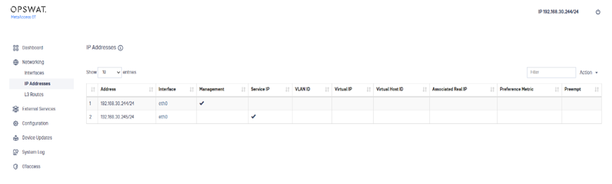
2) Double-click the current Management IP (indicated by a check in the Management column) to open a detail pane.
3) Open the Action menu and click Move Management.
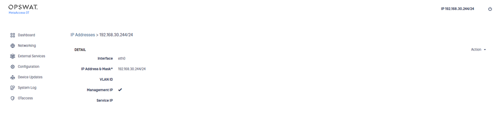
4) Enter the new IP address and port number and click the Submit button. The system will reboot.
After you perform the initial Management IP update, you can set a different IP address as the Management IP at any time. On the IP Addresses pane, double-click the IP you want to set as the Management IP. Then, open the Action menu on the detail pane, select Set Management IP , and click the Submit button. The system will reboot.
Configure the Service IP
The Service IP connects the Windows Client software on the Endpoint Gateway and the Remote User’s machine to the Management Console. There can be only one Service IP address.
1) Open the Networking menu and click IP addresses. The IP Addresses pane displays.
2) Open the Action menu and click Add IP Address.
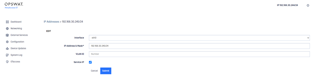
3) Type the following information:
- Interface : Physical / logical component that connects hardware to network(s).
- IP Address and Mask : Provide both an IP address and Mask.
- VLAN ID (optional): Optional for those operating in a VLAN environment.
- Service IP : Check to configure the IP address as the Service IP.
4) Click the Submit button.
The Console UI displays a message that the process was successful and displays the details for the new IP address.
To set the Service IP to a different IP address, double-click the desired IP address on the IP Addresses pane. Open the Action menu on the detail pane and select Edit. Check the Service IP checkbox to set this address as the Service IP.
Important
- If you change the Service IP to a different IP address, you also need to change the Service IP in Windows Client. Refer to the Installation and Administration Guide.
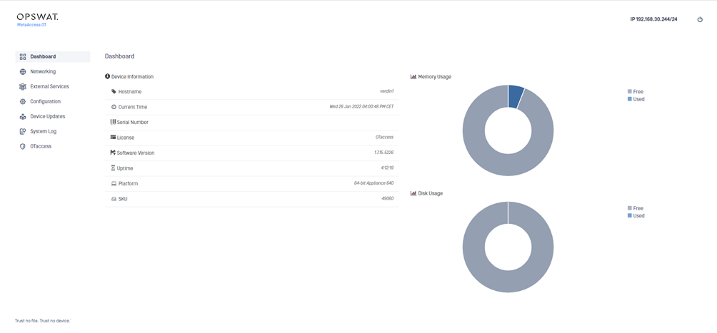
5 Management Console dashboard
When you log on to the Management Console, the Console UI dashboard displays the current status and metrics about the console. The Management IP address displays at the top.
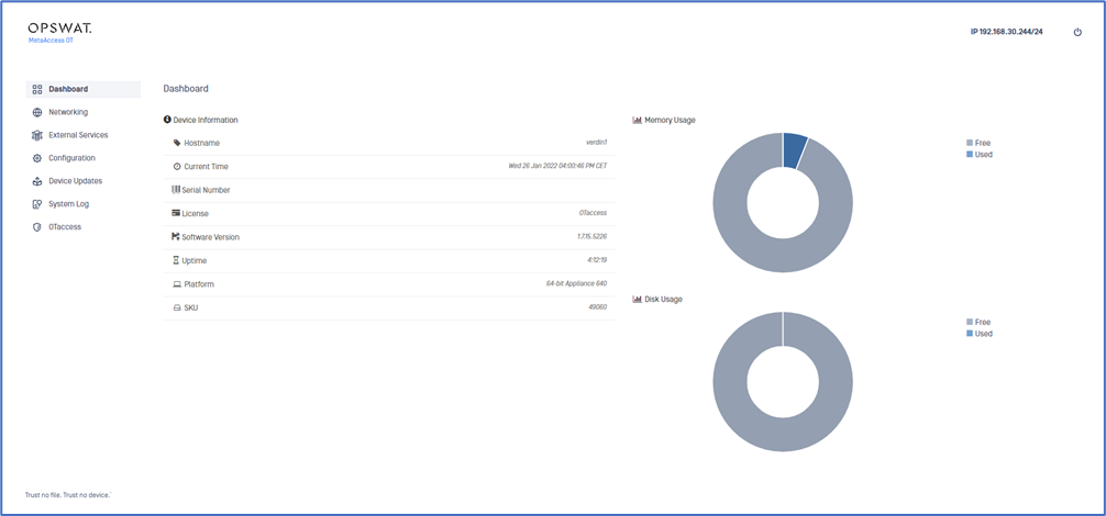
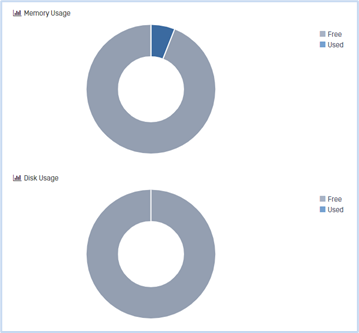
The Memory and Disk Usage reflects what is being used on this Secure OT Access onsite deployment.
Use the power icon drop down to reboot or halt the Management Console. The Reboot option restarts the console and Halt shuts down the console in a suspended state. If you select Halt , you will need to power-up the console.
6 Networking menu
Use the Networking menu options to view and manage network interfaces, IP addresses, and L3 routes for the Management Console.
Interfaces
Use the Interfaces option to manage the physical network interfaces and view information about the Management Console network hardware.
Before you start
- Port 1 needs to be the Management IP address.
View Interface information
Open the Networking menu and click Interfaces. The Interfaces pane displays the following:
- Short Name : Name of the interface
- Description : User-defined short text that describes the interface
- Mac Address : Unique ID assigned to the network interface
- MTU : Maximum Transmission Unit: the largest size packet or frame that can be sent through the network. The current values that can be selected are; 1500, 2000, 9000, 9216 or default ( 1500 ).
- OSPF Cost : Open Shortest Path First (OSPF) Cost is a basic routing metric.
- OSPF KeyId : Unique identifier for the OSPF configuration
- Pingable : Whether or not interface responds to a ping request, 0 means it’s disabled.
Edit an interface
1) Open the Networking menu and click Interfaces.
2) Click an interface name. A detail pane displays.
3) Open the Action menu on the detail pane and click Edit.
4) Edit the values as necessary.
5) Click the Submit button. The Console UI displays a message that the process was successful and displays the latest data.
Add IP address
IP addresses are added on a per-Interface basis, eth0 through the number of NICs in a system. You can add IP addresses though the Interfaces or IP Address option on the Networking menu.
Important
- You cannot add two IP addresses from the same subnet to different interfaces.
- For example, If Eth1 is bound to the 192.168.0.X network, then you cannot assign 192.168.0.X addresses to an interface other than Eth1.
1) Open the Networking menu and click Interfaces.
2) Click an interface name. A detail pane displays.
3) Open the Action menu on the detail pane and click Add IP Address.
4) Enter the following information:
- Interface : Physical / logical component that connects hardware to network(s).
- IP Address and Mask : Type both an IP address and subnet mask.
- VLAN ID (optional): 1 – 255
- Service IP (optional): Check to configure the IP address as a Service IP.
5) Click the Submit button.
A message displays that the process was successful.
Note
- The subnet mask is the network address plus the bits reserved for the subnetwork. The router performs this operation when it identifies a mask. Refer to “Subnet mask chart” for more information.
Add VIP address
VIP addresses are added on a per-Interface basis. Each VIP address can be bound to only one interface per machine. VIP addresses facilitate High Availability (HA) across two physically disparate Secure OT Access machines.
You can add VIP addresses though the Interface or IP Address menu options.
Important
- All new VIP Addresses must be associated to existing IP addresses.
1) Open the Networking and click Interfaces.
2) Click an interface name. A detail pane displays.
3) Open the Action menu on the detail pane and click Add VIP Address.
4) Enter the following information:
- Interface : Physical / logical component that connects hardware to network(s).
- IP Address and Mask : Type both an IP address and subnet mask
- VLAN ID : 1 - 255
- Service IP : Check to configure the address as a Service IP.
IP Addresses
Use the IP Addresses menu option to view and update the Management IP and Service IP.
Add IP or VIP address
1) Open the Networking menu and click IP Addresses. The IP Addresses pane displays.
2) Open the Action menu and click the appropriate option. Refer to “Add IP address” and “Add VIP address” for information.
Edit IP address
1) Open the Networking menu and click IP Addresses.
2) Click on an IP address. A detail pane displays.
3) Open the Action menu on the detail pane and click Edit.
4) Edit the values as necessary.
5) Click the Submit button.
Delete IP address
1) Open the Networking menu and click IP Addresses.
2) Click an IP address. A detail pane displays.
3) Open the Action menu on the detail pane and click Delete.
4) Click the Submit button to confirm your action.
Important
- You must move the Management IP to a different address before you can delete the Management IP address. Refer to “Update the Management IP”.
7 External Services menu
Use the External Services menu to configure options that allow users to access various functionalities.
Mail (SMTP) servers
Use the Mail (SMTP) Servers menu option to configure credentials to access Simple Mail Transfer Protocol (SMTP) servers. An SMTP server must be configured before a user can receive email.
Add Mail server
1) Open the External Services menu and click Mail (SMTP) Servers. The Mail Servers pane displays.
2) Open the Action menu and click Add Mail Server. A detail pane displays.
3) Type values in the following boxes:
- Server Name / IP Address : FQDN or IP address for server
- Description : User-defined description of the mail server
- Domain : Domain for mail server
- Port : Port to access the mail server. Common ports are 25, 465 and 587 (default).
- Auth Type : Defaults to None. Can be set to Plain, Login or CRAM MD5.
- Mail Form : Designated account from which to send mail from
- Username : Username of designated account which to send mail from
- Password : Password used with the account
- Enabled : Defaults to enabling the mail server
4) Click the Submit button.
Edit Mail server
1) Open the External Services menu and click Mail (SMTP) Servers.
2) Click a mail server. A detail pane displays.
3) Open the Action menu on the detail pane and click Edit.
4) Edit the values as necessary.
5) Click the Submit button.
Test Mail server credentials
1) Open the External Services menu and click Mail (SMTP) Servers.
2) Click a mail server. A detail pane displays.
3) Open the Action menu on the detail pane and click Test. A diagnostics pane displays.
4) Type the email address in the Email Address box.
5) Click the Submit button. The results of the test display in the lower pane.
Delete Mail server
1) Open the External Services menu and click Mail (SMTP) Servers.
2) Click a mail server. A detail pane displays.
3) Open the Action menu on the detail pane and click Delete.
4) Click the Submit button to confirm your action.
DNS servers
Use the DNS Servers menu option to add DNS servers that are monitored by the Management Console. A DNS server must be configured before the user can send and receive Short Message Service (SMS) notifications through Secure OT Access.
Important
- You must configure a DNS IP address before you set a cookie domain. If your cookie domain does not correspond to the DNS IP, users cannot log in to the Management Console. Refer to the Installation and Administration Guide for information on setting a cookie domain.
Add DNS server
1) Open the External Services menu and click DNS Servers. The DNS Servers pane displays.
2) Open the Action menu and select Add DNS Server. A detail pane displays.
3) Type values in the following boxes:
- IP Address : Server IP address
- Description : User defined description of the DNS server
- Enabled : Defaults to enabling the name server
4) Click the Submit button.
Edit DNS Server
1) Open the External Services menu and click DNS Servers.
2) Click a DNS server. A detail pane displays.
3) Open the Action menu on the detail pane and click Edit.
4) Edit the values as necessary.
5) Click the Submit button.
Delete DNS server
1) Open the External Services menu and click DNS Servers.
2) Click a DNS server. A detail pane displays.
3) Open the Action menu on the detail pane and click Delete.
4) Click the Submit button to confirm your action.
Remote Syslog
Use the Remote Syslog menu option to add credentials to Secure OT Access Remote Syslogs. A Remote Syslog must be configured before the user can view logs.
Add Remote Syslog
1) Open the External Services menu and click Remote Syslog. The Remote Syslogs pane displays.
2) Open the Action menu and select Add Remote Syslog Server. A detail pane displays.
3) Type values in the following boxes:
- IP Address : Location of Remote Syslog server
- Description : User-defined description of the Remote Syslog server
- Protocol : Choose from UDP or TCP
- Port : Default to port 514 for system logging (syslog).
- SSL Encrypted : Select if the Remote Syslog uses secure socket layer.
- Selector : Default value of local6.* but you can create a custom facility
- Enabled : Defaults to enabling the Remote Syslog Server
4) Click the Submit button.
Edit Remote Syslog
1) Open the External Services menu and click Remote Syslog.
2) Click a Remote Syslog. A detail pane displays.
3) Open the Action menu on the detail pane and click Edit.
4) Edit the values as necessary.
5) Click the Submit button.
Delete Remote Syslog
1) Open the External Services menu and click Remote Syslog.
2) Click a Remote Syslog. A detail pane displays.
3) Open the Action menu on the detail pane and click Delete.
4) Click the Submit button to confirm your action.
Time (NTP) Servers
Use the Time (NTP) Servers menu option to add a Time server that the Management Console can access and monitor. A Time server must be configured before the user can set the date and time on their host machine.
Add Time server
1) Open the External Services menu and click Time (NTP) Servers. The Time Servers pane displays.
2) Open the Action menu and click Add Time Server. A Time Server detail pane displays.
3) Type values in the following boxes:
- IP Address or Hostname : IP address of the private or public time server
- Description : User defined description of time server, location, purpose, etc.
- Min Refresh : Values in seconds, default to 60 seconds (1 minute)
- Max Refresh : Values in seconds, default to 3600 seconds (1 hour)
- Enabled : Defaults to enabling the time server
4) Click the Submit button.
Edit Time Server
1) Open the External Services menu and click Time (NTP) Servers.
2) Click a time server. A detail pane displays.
3) Open the Action menu on the detail pane and click Edit.
4) Edit the values as necessary.
5) Click the Submit button.
Delete Time server
1) Open the External Services menu and click Time (NTP) Servers.
2) Click a time server. A detail pane displays.
3) Open the Action menu on the detail pane and click Delete.
4) Click the Submit button to confirm your action.
8 Configuration menu
Use the Configuration menu options to control user accounts, licenses, notifications, lockouts, date/time, and backups.
Before you start
- Only an administrator can access the Configuration menu.
Settings
Use the Settings menu option to view and update Management Console information.
1) Open the Configuration menu and click Settings. The Settings pane displays.
2) Click a setting name to open a pane where you can change the values:
- SSH Port : Secure Shell (SSH) is a cryptographic network protocol that lets network services operate securely over an unsecured network. The standard TCP port is 22.
- Hostname : Label specified for the device. This name is used in events and logs.
- Date Time : System time and date
- Time Zone : Local zone for the appliance’s location
- Login Message : Text that shows after a user logs on the appliance
- Session Timeout : Number of minutes that a session can stay open
- Notification Email Addresses : Email addresses where notifications will be sent
3) Click the Save or Submit button to save your changes.
User Accounts
Use the User Accounts menu option to create and manage accounts for users accessing the Management Console. This option does not apply to user accounts for the Admin UI.
Add user account
1) Open the Configuration menu and click User Accounts. The User Accounts pane displays.
2) Open the Action menu and select Add User Account. A detail pane displays.
3) Type values in the following boxes:
- Username : User defined name for the account; white spaces are not allowed.
- Password : At least 7 alphanumeric and the following special characters (- _.! $ *)
- Description : User defined description of the account
- Email Address : User’s primary email address
- Force Password Reset : Forces users to reset password on next login
- Enabled : Defaults to enabling the user account
4) Click the Submit button.
Edit, change password, or delete user account
1) Open the Configuration menu and click User Accounts.
2) Click the user you want to edit or delete. A detail pane displays.
3) Open the Action menu on the detail pane and click Edit , Change Password , or Delete.
- Edit : Change the description or email address for the user account or force a password reset. Click the Submit button.
- Change Password : Type and confirm the new password in the Password boxes. Click the Submit button.
- Delete : Click the Submit button to confirm your action.
Login Attempts
Use the Login Attempts menu option to manage lockout parameters for failed login attempts and reset locked-out users.
This option applies only to login attempts on the Management Console. It does not apply to login attempts for the Admin UI.
When you click Login Attempts , the Login Attempts pane displays and lists all the users and their locked-out status. Open the Actions menu and select Clear to remove the locked status.
License
Use the License menu option to view, update, or delete the Secure OT Access license.
Note
- The License menu refers to the license for the entire Secure OT Access product. Any changes will impact all components of the
product.
When you click License , the License pane displays the following details:
- License Type : Full or Evaluation
- Customer name
- Organization : Name of the organization
- Identifier : Identifying number (i.e., serial number)
Update license
1) Open the Configuration menu and click License.
2) Open the Action menu and click Update. The License Upload pane displays.
3) Click Choose File in the Local License File box to locate the new license file.
4) Click the Upload License button to upload the license.
Delete license
1) Open the Configuration menu and click License.
2) Open the Action menu and click Delete.
3) Click the Submit button to confirm your action.
SSL/TLS Credentials
Use the SSL/TLS Credentials menu option to update the Single Socket Layer (SSL) or Transport Layer Security (TLS) certificates.
OPSWAT provides a default certificate, signed by the Certificate Authority (CA), so you can use the Management Console ‘out of the box’. You can add or update these certificates as you wish, although if you are going to use them outside your plant, they must be signed by the CA.
If you are using clientless services with the HTTPS protocol, you MUST create an additional signed certificate for that protocol.
See current credentials
Open the Configuration menu and click SSL/TLS Credentials. The SSL/TLS Credentials pane displays the current certificates. You can view the following information:
- Common Name : Username for the Management Console. This should be part of the fully distinguished name shown in
- Subject*.
- Subject : Fully distinguished name of the location of the Management Console
- Number of Certificates : Certificates attached to the Management Console
- Status : Whether the certificates can be used. If a certificate is signed, the status will show as ‘Certified/Usable’
Create a certificate
Use the following procedures to create a certificate:
Create local keypair
1) Open the Configuration menu and click SSL/TLS Credentials.
2) Open the Action menu and click Create Local Keypair. A detail pane displays.
3) Type values in the following boxes:
- Key strength (bits) : Select a value from the dropdown list. The default is 2048.
- Subject (CN) (Required): The fully distinguished name of the Management Console. This value should be the same as the
- Subject* on the SSL/TLS Credentials pane.
- Organization : Name of your organization
- Department : Department in your organization that is receiving the key pair.
- City where your organization is located.
- State/Province where your organization is located
- Country (Required) where your organization is located.
4) Click the Submit button.
Warning
- You can only use a certificate associated with a local keypair in your company’s intranet.
Import key pair
You can import the public key from a key pair created with a third-party tool.
1) Open the Configuration menu and click SSL/TLS Credentials.
2) Open the Action menu and click Import Keypair. A detail pane displays.
3) Type values in the following boxes:
- Private Key Pair Passphrase : Text used to control access to the private key
- Private Key Pair : Characters of the private key in the key pair
- Certificate : Characters making up the certificate associated with the key pair
- Intermediary Certificate (Optional): Characters making up the intermediary key pair
- Enabled : Click to enable the certificate.
4) Click the Submit button.
Important
- You must import a key pair created by a Certificate Authority to use an associated certificate outside of your company’s intranet.
Set SSL key for admin GUI
You can associate the certificate configured on the Management Console with the Admin UI.
1) Open the Configuration menu and click SSL/TLS Credentials.
2) Open the Action menu and click Set SSL key for admin GUI. A detail pane displays.
3) Select a certificate from the dropdown list.
4) Click the Submit button.
Associate certificate
You can associate a certificate with a specified Management Console.
1) Open the Configuration menu and click SSL/TLS Credentials.
2) Click the name of the Management Console. A detail pane displays.
3) Open the Action menu on the detail pane and click Add Certificate. An edit pane displays.
4) Paste the characters of the certificate into the Certificate box.
5) Click the Submit button.
Edit certificate
Certificates must be enabled to function and are enabled by default. You can disable a certificate and re-enable it later.
1) Open the Configuration menu and click SSL/TLS Credentials.
2) Click the name of the credential. A detail pane displays.
3) Open the Action menu on the detail pane and click Edit.
4) Click to enable or disable the certificate.
5) Click the Submit button.
Delete certificates
You can delete all certificates from the Management Console.
1) Open the Configuration menu and click SSL/TLS Credentials.
2) Click the name of the Management Console. A detail pane displays.
3) Open the Action menu on the detail pane and click Delete certificates.
4) Click the Submit button to confirm your action.
Delete certificate
You can delete an individual certificate.
Warning
- Deleting the certificate also deletes the key pair.
1) Open the Configuration menu and click SSL/TLS Credentials.
2) Click the name of the Management Console. A detail pane displays.
3) Open the Action menu on the detail pane and click Delete.
4) Click the Submit button to confirm your action.
Security Management
Use the Security Management options to protect against malicious port scan detection attacks on traffic flowing through the Management Console. IP addresses that conduct overt scans (FIN/XMAS/NULL scans) are blocked immediately. Malicious activity can be configured for obscure scans. These can consist of a source IP scanning anomalous number of ports or the scanning of one specific port an irregular number of times.
You can manually block IP addresses by adding them to a blacklist or unblock them by adding them to a whitelist. IPs that have been blocked past a specific amount of time can be unblocked via a clean-up process.
Security Configuration
Use the Security Configuration menu option to set thresholds and values to determine when to treat activity as malicious. The thresholds are integer count values, time in seconds, or specific ports. Thresholds surpassed by any given host are treated as malicious activity.
Open the Configuration menu, then click Security Management and Security Configuration to display the Security Configuration pane. You can configure the following values:
- Port Scan Threshold : Threshold count of hits per unique port during analysis of host activity
- Single IP Scan Threshold : Threshold count of ports scanned during analysis of host activity
- Overall Port Scan Threshold : Threshold count of collective activity during analysis of host activity. Collective activity is based on combinations of actions, for example if one host hits port 23 four times and ports 80,443,8080,9000,9090 each once.
- Last Seen Delta (Integer Seconds): Secure OT Access processes will block hosts that have last been seen within (less than) this value.
- Lockout Time (Integer Seconds): If a host has been blocked by Security Management for a period longer than this value, it will be unblocked.
- Ports to Ignore : Comma delimited string of ports for Security Management to ignore while processing live network traffic. A range of ports is supported if the format is properly used (x-y). Example (note no white spaces when specifying a range): ports_to_ignore:22,443,80-90,8080,8443-8448,502.
- Hot Ports : Comma delimited string of ports for Security Management to immediately create a block action (of the relevant src ip) upon encountering.
- Enabled : Click to enable the settings.
Notes
- Ports to Ignore will always include ports 6446 and 443
- The following Ports to Ignore are included by default: 80, 443, 8443, and 22
- The same port cannot be in both Ports To Ignore and Hot Ports at the same time
Blocked IPs
Use the Blocked IPs menu option to view and manage IP addresses blocked by Security Management.
Unblock IP address
1) Open the Configuration menu, then click Security Management and Blocked IPs. The Security Blocked IP Management pane displays.
2) Select an IP address.
3) Open the Action menu and click Unblock Selected.
4) Click the Submit button to confirm your action.
Warning
- You cannot use this procedure to unblock IP addresses on the blacklist. Refer to “Blacklisted IPs” for more information.
Whitelisted IPs
Use the Whitelisted IPs menu option to manage IP addresses that are considered privileged by the organization. Activity from these IP addresses should not be considered malicious.
Add IP to Whitelist
1) Open the Configuration menu, then click Security Management and Whitelisted IPs. The Security Whitelisted IP Management pane displays.
2) Open the Action menu and select Add Custom IPs. A detail pane displays.
3) Enter an IP address as an octet.
4) Click the Submit button.
Delete IP from Whitelist
1) Open the Configuration menu, then click Security Management and Whitelisted IPs. The Security Whitelisted IP Management pane displays,
2) Select an IP address.
3) Open the Action menu and select Delete Selected.
4) Click the Submit button to confirm your action.
Blacklisted IPs
Use the Blacklisted IPs menu option to view IP addresses that are blocked or denied during monitoring. Activity from these IP addresses is considered malicious.
Add IP to Blacklist
1) Open the Configuration menu, then click Security Management and Blacklisted IPs. The Security Blacklisted IP Management pane displays.
2) Open the Action menu and select Add Custom IPs.
3) Enter an IP address as an octet.
4) Click the Submit button.
Delete IP from Blacklist
1) Open the Configuration menu, then click Security Management and Blacklisted IPs. The Security Blacklisted IP Management pane displays.
2) Select an IP address.
3) Open the Action menu and select Delete Selected.
4) Click the Submit button to confirm your action.
Login Lockout Configuration
Use the Login Lockout Configuration menu option to configure the following settings for Management Console users.
- Max Failed Attempts : Number of failed attempts tolerated by this console. This value must be greater than 1. If a user exceeds this value, they will receive a notification regarding the attempts. The notification will contain a link the user can click to change their password and a separate link to report a possible attack if the user is not trying to login. If the user clicks the link for a security attack, a notification is sent to the superadmin.
- Locked Duration : Number of minutes a user is locked out of the Management Console when a suspected attack is detected. This value must be greater than 1.
Manage locked accounts
1) Open the Configuration menu and click Login Lockout Configuration. The Login Lockout Configuration pane displays.
2) Open the Action menu and select Manage Locked Accounts. The Login Attempts pane displays. Refer to “Login Attempts” for more information.
Reset to default configuration
1) Open the Configuration menu and click Login Lockout Configuration. The Login Lockout Configuration pane displays.
2) Open the Action menu and select Reset to Default Configuration. The Max Failed Attempts and Locked Duration boxes reset to their original values.
Backups
Use the Backups menu option to display a list of the backups of the Secure OT Access software with descriptions, timestamp, and the backup system generated name.
Note
- Backups apply to the software on the Management Console and on the Admin UI.
Apply a backup
There are two ways to apply a backup.
1) Open the Configuration menu and click Backups. The Backup Configs pane displays.
2) Do one of the following:
- Click Apply at the end of a backup row on the Backup Configs pane.
- Click on a backup in the Backup Configs pane to open a detail pane. Open the Action menu in the detail pane and click
- Apply*. Then, click the Submit button.
Snapshot Running Config
You can apply a snapshot that was captured previously on the Management Console. The snapshots are stored locally but can be exported.
1) Open the Configuration menu and click Backups. The Backup Configs pane displays.
2) Open the Action menu and select Snapshot Running Config. A detail pane displays.
3) Type a comment regarding the snapshot and click the Submit button.
Export a backup
Exporting a backup converts the configuration into an AES 256-bit encrypted binary format by applying a password to it. The password must be 8 characters minimum.
1) Open the Configuration menu and click Backups.
2) Select a backup. A detail pane displays.
3) Open the Action menu on the detail pane and click Export.
4) Enter and confirm the password for the encrypted file in the Password boxes.
5) Click the Submit button.
Delete a backup
Deleting a backup configuration removes the backup from the Management Console.
1) Open the Configuration menu and click Backups.
2) Select a backup. A detail pane displays.
3) Open the Action menu and click Delete.
4) Click the Submit button to confirm your action.
Upload
Use the Backup Configs pane to upload a configuration file from an external resource.
1) Open the Configuration menu and click Backups. The Backup Configs pane displays.
2) Open the Action menu and select Upload. A detail pane displays.
3) Click Choose File in the Local Filename or config box and browse to select a file.
4) Enter a password that was used to decrypt the file in the Password box.
5) Click the Upload Config button.
9 Software menu
Use the Software menu to manage versions (personalities) of the Management Console software and upload new personalities. You are provided instructions on the format of the file that needs to be uploaded and what steps they should take. You can also see current build for the appliance.
Upload software
Use the Software pane to upload software from a local machine to the Management Console.
1) Open the Software menu. The Software pane displays.
2) Open the Action menu and click Upload Software. A detail pane displays.
3) Click Choose File in the Local Filename of update package box.
4) Browse to locate and select the file.
5) Click the Upload Package button.
Apply personality
After uploading, you must apply the new personality and the Management Console must reboot before the new personality is put into use.
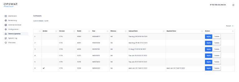
1) Open the Device Updates menu. The Device Updates pane displays.
2) Click Apply in the row of the personality you want to use.
Delete personality
Before you start
- Only a SysAdmin can delete personalities.
1) Open the Software menu. The Software pane displays.
2) Click Delete in the row of the personality you want to delete.
3) Click the Submit button to confirm your action.
10 System Log menu
Use the System Log menu to display the Management Console System Log.
The default System Log pane provides a paginated, non-refreshing view of the local device syslog. The data displayed is presented in reverse chronological (newest first) order. You can set filters to view specific subsets of information about events encountered by the Management Console.
The initial System Log pane provides unfiltered events going through the Management Console.
You can perform the following tasks from the System Log pane.
Add type filter
You can create filtered views by selecting from a pre-defined list of available filters.
1) Open the System Log menu. The System Log pane displays.
2) Open the Action menu and click Add Type Filter. A detail pane displays.
3) Select a filter from the Filter Type dropdown list on the detail pane. Built-in filters include:
- Admin GUI : Displays the GUI for administrators
- Bridging : Filters for “tbridge2” events
- Policy : Users can add the type of policy to filter against such as: just.http, yara.report and other policies added onto the appliance
- Proxying : Filters for “tproxd” events
- Rule : Filters for rules with a UUID
- System : Filters for events with “skeyd” that starts a system
Add Regex filter
1) Open the System Log menu. The System Log pane displays.
2) Open the Action menu and click Add Regex Filter. A detail pane displays.
3) Click to select Exact Match or Regular Expression for searching a pattern in the log file.
4) Type an expression in the box.
5) Click the Submit button.
Export log results
You can export results with or without encryption. The encrypted file must have a password assigned to it and will be slightly larger than the unencrypted file. The default saved file name is “OPSWAT_skey_syslog.gz”
1) Open the System Log menu. The System Log pane displays.
2) Open the Action menu and click Export. A detail pane displays.
3) Click yes to encrypt the file or no to export the file without encryption.
4) Enter and confirm a password in the Password boxes (required for encrypted files).
5) Click the Submit button.
Refresh
You can update the software to see the latest files.
1) Open the System Log menu. The System Log pane displays.
2) Open the Action menu and click Refresh. The displayed software updates.
Appendix A Subnet mask chart
The subnet mask is the network address plus the bits reserved for the subnetwork. The router performs this operation when it identifies a mask.
| # Bits (Mask) | Addresses | Usable Hosts | Netmask | Classes |
|---|---|---|---|---|
| /32 | 1 | 1 | 255.255.255.255 | |
| /30 | 4 | 2 | 255.255.255.252 | Single IP Address |
| /29 | 8 | 6 | 255.255.255.248 | Single IP Address |
| /28 | 16 | 14 | 255.255.255.240 | Single IP Address |
| /27 | 32 | 30 | 255.255.255.224 | Single IP Address |
| /26 | 64 | 62 | 255.255.255.192 | Single IP Address |
| /25 | 128 | 126 | 255.255.255.128 | Single IP Address |
| /24 | 256 | 254 | 255.255.255.0 | Class C Network |
| /23 | 512 | 510 | 255.255.254.0 | Class C Network |
| /22 | 1024 | 1022 | 255.255.252.0 | Class C Network |
| /21 | 2048 | 2046 | 255.255.248.0 | Class C Network |
| /20 | 4096 | 4094 | 255.255.240.0 | Class C Network |
| /19 | 8192 | 8190 | 255.255.224.0 | Class C Network |
| /18 | 16384 | 16382 | 255.255.192.0 | Class C Network |
| /17 | 32768 | 32766 | 255.255.128.0 | Class C Network |
| /16 | 65536 | 65534 | 255.255.0.0 | Class B Network |
| /15 | 131072 | 131070 | 255.254.0.0 | Class B Network |
| /14 | 262144 | 262142 | 255.252.0.0 | Class B Network |
| /13 | 524288 | 524286 | 255.248.0.0 | Class B Network |
| /12 | 1048576 | 1048574 | 255.240.0.0 | Class B Network |
| /11 | 2097152 | 2097150 | 255.224.0.0 | Class B Network |
| /10 | 4194304 | 4194302 | 255.192.0.0 | Class B Network |
| /9 | 8388608 | 8388606 | 255.128.0.0 | Class B Network |
| /8 | 16777216 | 16777214 | 255.0.0.0 | Class B Network |
Appendix B Hardware description
The Management Console consists of a DELL PowerEdge R240 entry-level single-socket rack server. The console is to be mounted in a 1U rack, using the included rail kit.
The Dell has the following parameters:
Depth: 534.5 mm
Width:
- 482.0 mm (with rack latched)
- 434.0 mm (without rack latched)
Height: 42.8 mm
Weight: 12.2 KG
A power cable is included with the Dell.
Appendix C Regulatory compliance and certification
Each Dell EMC PowerEdge 204 unit is UL and CE approved.
Each unit has an EMC Emissions Class of A and has been determined to be compliant with the applicable standards, regulations, and directives for the countries where the product is marketed. It is intended for use in non-residential/non-domestic environments.
The associated power cable is suitable for the intended country of delivery. Products that are relocated to other countries should use nationally certified power cords and plus to ensure safe operation of the product.