Prerequisites
Parameter | Limits |
|---|---|
Temperature | -10-35ºC Operating -40-65ºC Non-Operating |
Humidity | 5-95% non-condensing, Non-Operating 10-80% RH, Operating |
Item | Limits |
|---|---|
Type / Watts | 250 Watts |
Hardware requirements
If any items you are supposed to receive are missing or damaged, contact Support.
You will receive a package from OPSWAT containing the following:
Two 1U servers.
Mounting rail kits.
Two power cables.
Fiber Optic cable.
Two security dongles.
In addition, you must have:
Flathead screwdriver.
Ethernet cables.
The installation location must provide:
Access to the USB port on the NetWall Diode BLUE node. Ports are available on the front and back of the node.
2 x 1U rack space.
250 Watts power in the rack where the nodes will be installed.
Installation procedure
NetWall Diode node installation includes the following steps:
Install the servers in the rack.
Connect the servers to your system.
Connect the servers to each other.
Power up each node.
Install servers in the rack
Install each server in the rack with the supplied mounting rails, following your local procedures.
The sides containing the USB ports should be toward the front of the rack. You will insert a dongle in the USB port of the NetWall Diode BLUE node and the Windows Host computer.
Connect servers to you system
The following graphic shows the rear view of the server.
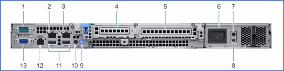
Use the following table to connect both servers to your system. You will not need all of the connections for the NetWall Diode installation.
Port Number | Description | NetWall connection |
|---|---|---|
1 | Serial port | N/A |
2 | NIC port (Gb 1) | NetWall BLUE: Connect to the trusted network with an Ethernet cable. NetWall RED: Connect to the untrusted network with an Ethernet cable. |
3 | NIC port (Gb2) | N/A |
4 | Half-height PCIe expansion card slot | Connect NetWall Diode BLUE to NetWall Diode RED with the fiber optic cable. See the following section for instructions and precautions. |
5 | Full-height PCIe expansion card slot | N/A |
6 | Power supply unit | Connect NetWall BLUE and NetWall RED to their power supplies with the power cables. |
7 | PSU Built-in Self Test (BIST) LED | N/A |
8 | PSU Built-in Self Test (BIST) button | N/A |
9 | System identification button | N/A |
10 | System status indicator cable port (CMA) | N/A |
11 | USB 3.0 ports (2) | N/A |
12 | iDRAC dedicated NIC port | N/A |
13 | VGA port | N/A |
Connect servers to each other
Use the fiber optic cable to connect the servers to each other. Install the cable connector on each end of the fiber optic cable into the connector, indicated by ‘4’ on the above table, on each server.
Make sure both servers are powered off before connecting them.
Stand on an electrostatic mat to connect the nodes.
Computer cables should always use strain relief to protect the connected equipment from excessive force via the cable. This is especially important for cables between racks.
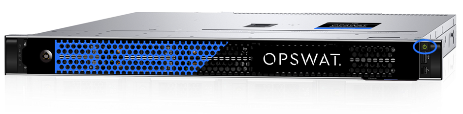
Power up NetWall nodes
Press the power button on each NetWall Diode node (NetWall Diode BLUE is shown below) to power up the node. Press each power button a second time to shut down that node.