Version | Date of change | Author | Summary of change |
|---|---|---|---|
1.0 | Oct 17th, 2023 | Miguel Angel Fernández | Initial version |
1.1 | Dec 15th, 2023 | Miguel Angel Fernández | Ammend of errors reported in CC evaluation. New pictures included |
1.2 | May 8th, 2024 | Miguel Angel Fernández | Document Title Changed. Some pictures have been updated |
USG-100 Setup
Prerequisites
Parameter | Limits |
|---|---|
Temperature | -10-35ºC Operating -40-65ºC Non-Operating |
Humidity | 5-95% non-condensing, Non-Operating 10-80% RH, Operating |
Item | Limits |
|---|---|
Type / Watts | 250 Watts |
Hardware requirements
If any items you are supposed to receive are missing or damaged, contact Support.
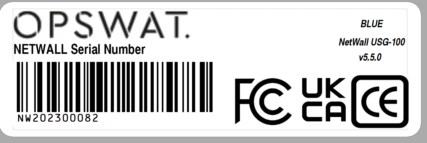
You can check the product reference in the included label in each one of the nodes as indicated in the picture:
You will receive a package from OPSWAT containing the following:
Two 1U servers.
Mounting rail kits.
Two power cables.
One PV.
Two security dongles.
In addition, you must have:
Flathead screwdriver.
Ethernet cables.
The installation location must provide:
Access to the USB port on the NetWall USG-100 BLUE node. Ports are available on the front and back of the node.
2 x 1U rack space.
250 Watts power in the rack where the nodes will be installed.
USG-100 and its components should be installed within secure and controlled access facilities, preventing unauthorized access.
Installation procedure
Please, before installing and configuring OPSWAT NetWall USG-100 follow these considerations:
1. USG-100 and its components should be installed within secure and controlled access facilities, preventing unauthorized access.
2. Installation and configuration should be done only by personnel with authorized physical access to USG-100.
3. Once installed, USG-100 should be the only communications channel between sending and receiving networks.
NetWall USG-100 installation includes the following steps:
Install the servers in the rack.
Connect the servers to your system.
Connect the servers to each other.
Power up each node.
Install servers in the rack
Install each server in the rack with the supplied mounting rails, following your local procedures.
The sides containing the USB ports should be toward the front of the rack. You will insert a dongle in the USB port of the NetWall USG-100 BLUE node and the Windows Host computer.
Connect servers to you system
The following graphic shows the rear view of the server.
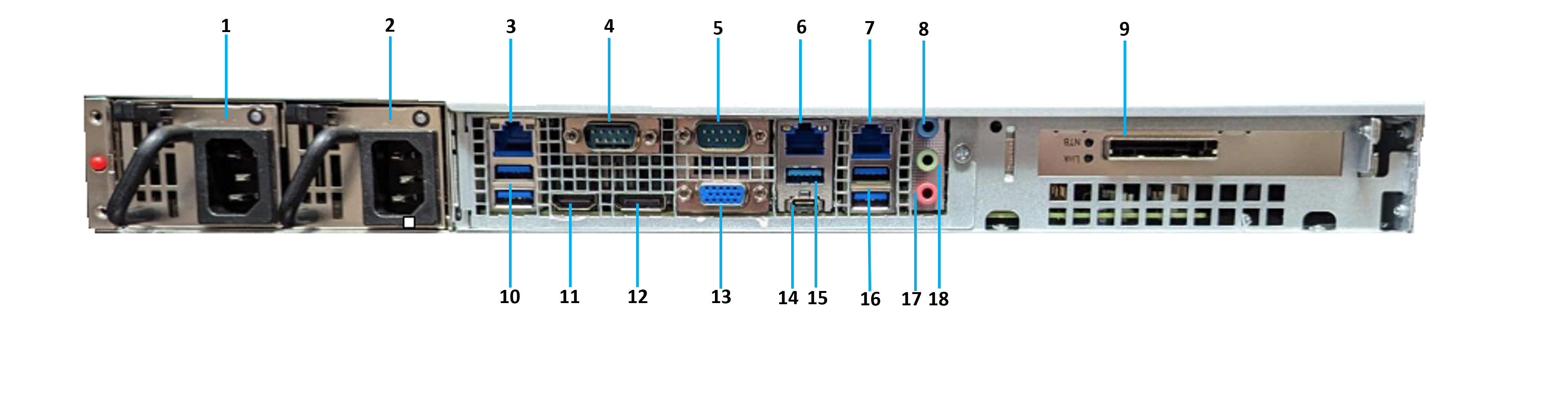
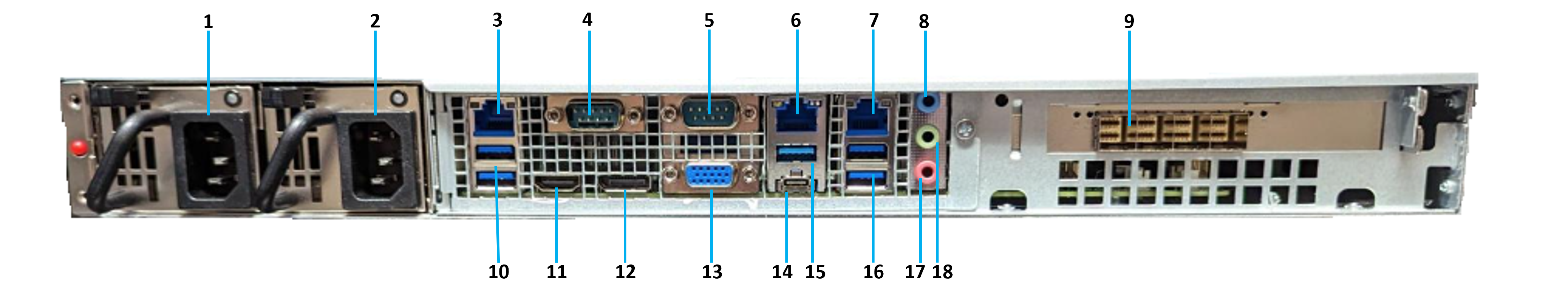
Use the following table to connect both servers to your system. You will not need all of the connections for the NetWall USG-100 installation.
Port Number | Description | NetWall connection |
|---|---|---|
1 | Power supply Unit | Connect NetWall BLUE and NetWall RED to their power supplies with the power cables. |
2 | Redundante Power supply Unit | Connect NetWall BLUE and NetWall RED to their power supplies with the power cables. |
3 | RJ45 LAN Port (LAN3) | N/A. |
4 | COM Port (COM1) | N/A. |
5 | COM Port (COM2) | N/A. |
6 | RJ45 LAN Port (LAN2) | N/A. |
7 | RJ45 LAN Port (LAN1) | NetWall BLUE: Connect to the trusted network with an Ethernet cable. NetWall RED: Connect to the untrusted network with an Ethernet cable. |
8 | Line In | N/A |
9 | PCIe card slot | |
10 | USB 3.2 Gen 2 Ports | N/A. |
11 | HDMI Port (HDMI1) | Connect to a HDMI monitor to access the CLI. |
12 | DisplayPort (DP1) | N/A. |
13 | D-Sub Port (VGA1) | Connect to a VGA monitor to access the CLI. |
14 | USB 3.2 Gen 2 Port Type-C Port | N/A. |
15 | USB 3.2 Gen Port | N/A. |
16 | USB 3.2 Gen 2 Ports | N/A. |
17 | Line Out | N/A. |
18 | Microphone | N/A. |
Connect servers to each other
Use the PCI cable to connect the servers to each other. Install the cable connector on each end of the PCI cable into the connector, indicated by ‘9’ on the above table, on each server. This connection have to be the only one between the both networks we want to segment.
Make sure both servers are powered off before connecting them.
Stand on an electrostatic mat to connect the nodes.
Computer cables should always use strain relief to protect the connected equipment from excessive force via the cable. This is especially important for cables between racks.
Power up NetWall nodes
Press the power button on each NetWall USG-100 node to power up the node. Press each power button a second time to shut down that node.
USG-100 Initial Configuration
You need a security dongle inserted in the server which configuration you want to change, RED or BLUE.
Default IP
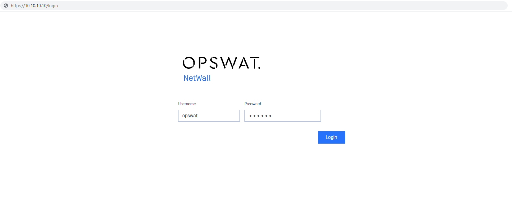
Netwall USG-100 comes with a default IP of 10.10.10.10 to access the management UI. This is applicable for both sides BLUE and RED, so notice that you have to configure both sides.
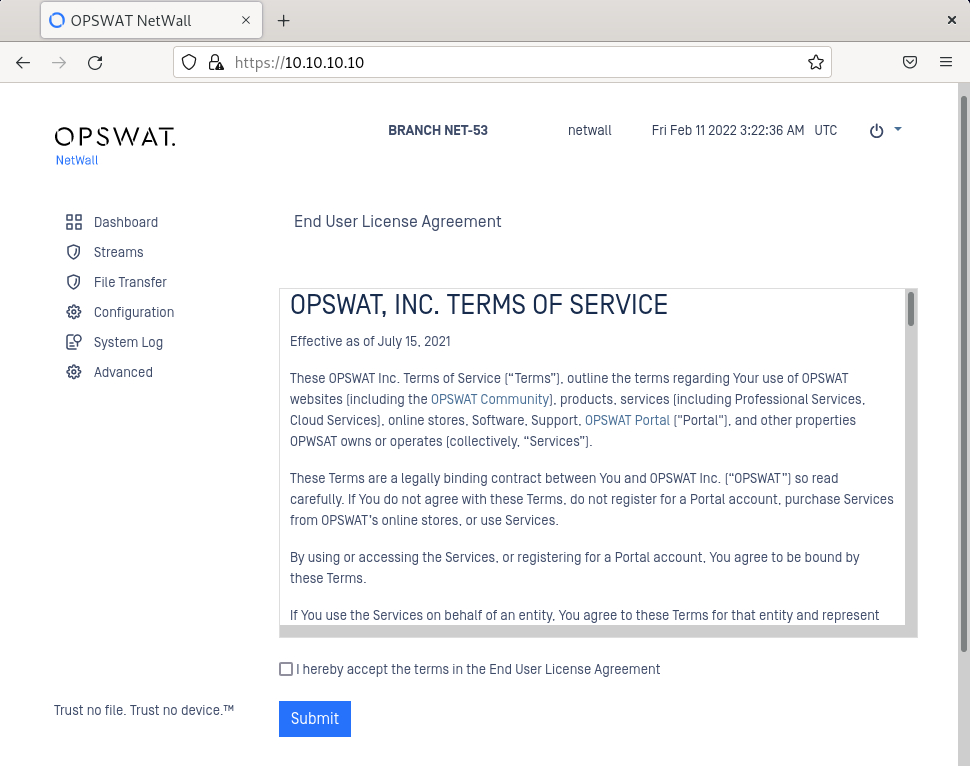
Configure a laptop/desktop with a 10.10.10.X network address. Open a web browser and type https://10.10.10.10 to access the web UI. Once in the login page, insert valid user/password.
Default credentials are opswat/a1aaaa. Please, change it as soon as possible
After login, user would need to accept the EULA
IP Addresses
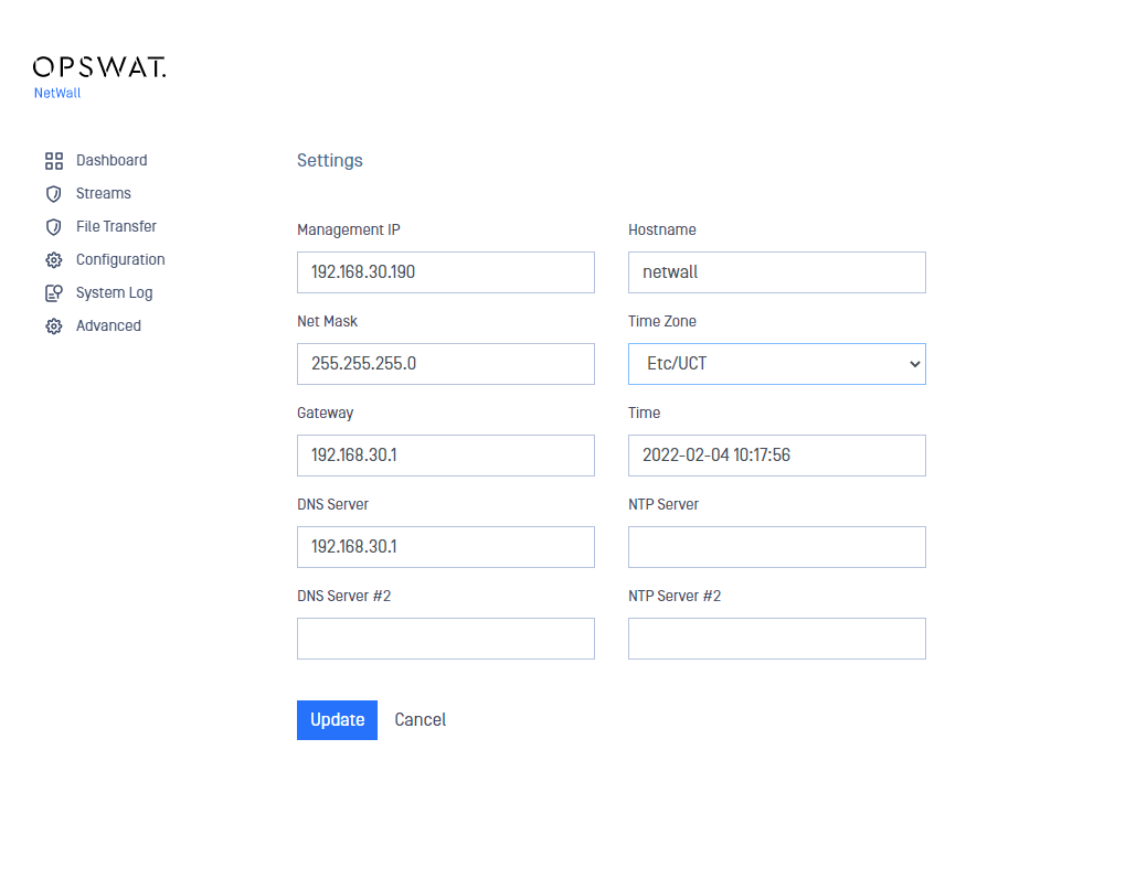
After accepting the EULA, user will be redirected automatically to Settings page, where he/she will be prompted to insert the management IP and other connection details.
Fill in Management IP (for instance 192.168.30.244).
Fill in Net Mask (for instance 255.255.255.0)
Fill in Gateway (for instance 192.168.30.1)
Click Update to save the changes.

When changing Management IP, the system will reboot. Simply wait until the device reboots.
Licensing
Before being able to activate the license. User needs to be registered in my.opswat.com. Registration is free.
OPSWAT Netwall USG-100 needs to be licensed to be fully operational. In this section we will show how to get a valid license file and how to apply it to your NetWall system.
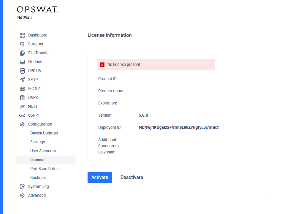
First thing is to check the Deployment ID. This ID can be found in Configuration -> License. Deployment ID needs to be copied as we will need it to get a valid license file.
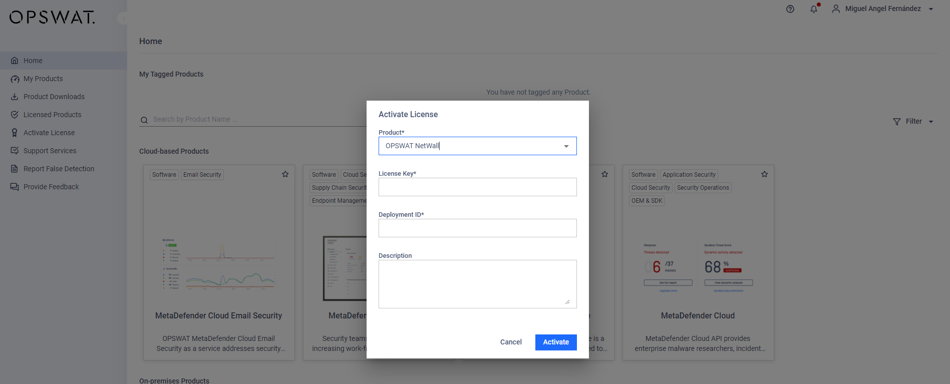
Then browse to my.opswat.com and login with your user/password. Once correctly logged in, click on Activate License and fill in the following fields:
Product: Select OPSWAT NetWall from the dropdown.
License Key: Insert the Activation Key that your OPSWAT sales representative has provided you with.
Deployment ID: Paste the Deployment ID you've copied in the previous step
Description: In this optional field, a description for the license key can be included.
Once filled in click on Request Unlock Key button and then click on Download Unlock Key to get the license file.
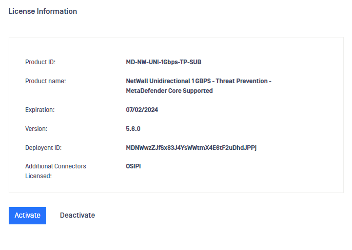
Once you have the Unlock Key file, we need to come back to NetWall USG-100 UI to activate the key. Go to Configuration -> License and click on Activate.
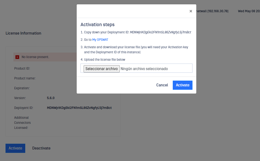
Click on Select File and browse to the Activation Key we have stored in the previous step. Then click on Activate. Once Active, you will be able to see new information in the fields Product ID, Product Name and Expiration.
USG-100 CLI
Alternatively, you can set up the Management IP and L3 Routes using NetWall USG-100 CLI connecting a monitor and a keyboard to each server, BLUE and RED.
Remember you can check available commands typing ?
Login with valid credentials and set up L3 route and management IP. After that, you can access to the management UI using the configured management IP and configure DNS and NTP servers.
Set up routes
eagle> config
eagle (config)> routes
eagle (config.routes)> add
eagle (config.routes.add)> gateway 192.168.X.X
eagle (config.routes.add)> target_range 0.0.0.0/0
eagle (config.routes.add)> save
Set up management IP and port
eagle> management
eagle (mgmt)> ipaddress 192.168.X.X/24
It will ask you to reboot, type 'y' and press 'enter'.
Set up DNS and NTP Servers
Once you have configured the management IP you can access the web UI to configure DNS and NTP servers.
DNS servers
Go to Configuration-> Settings
Click on Edit button
Type the IP address of the DNS server
Type the IP address of the DNS server 2 for an alternative DNS server
Click on Update button to save the changes
NTP servers
Go to Configuration-> Settings
Click on Edit button
Type the IP address of the NTP server. Network Time Protocol (NTP) lets the clocks synchronize between computer systems through packet-switched, variable-latency data networks
Type the IP address of the NTP server 2 for an alternative NTP server
Click on Update button to save the changes
Time manual configuration
There can be situations when configuring an NTP server is not possible (BLUE side with no Internet access, for instance). In this situations, admins can configure the Time manually:
Go to Configuration-> Settings.
Click on Edit button.
Select the time zone in the dropdown list.
Click on Time field and select day and time in the deployed calendar, then Apply.
Click on Update button to save the changes.
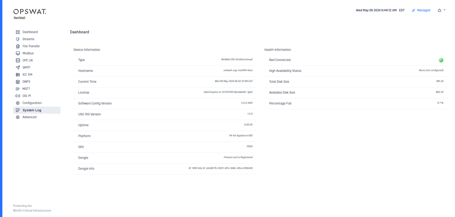
USG-100 Dashboard
Once correctly set up and configured, the user can check NetWall's status in the Health Information section in NetWall USG-100 RED Dashboard, where it can be checked if NetWall USG-100 BLUE is correctly connected.
Common Criteria Certified Software and Update process
The certified USG-100 software versions for BLUE and RED nodes are the following:
USG-100 Version BLUE: 1.0.0
USG-100 Version RED: 1.0.0
The user can check the current version running in the system checking NetWall Dashboard in both sides, RED and BLUE.
If the certified software is not the current one preloaded in the system, the user can update both appliances with the right software that could be downloaded from my.opswat.com.
Software Updates
You need a security dongle inserted in the server which configuration you want to change, RED or BLUE. You need to update both sides BLUE and RED independently.
You can easily update the software from the management UI.
Login using right credentials in the management UI
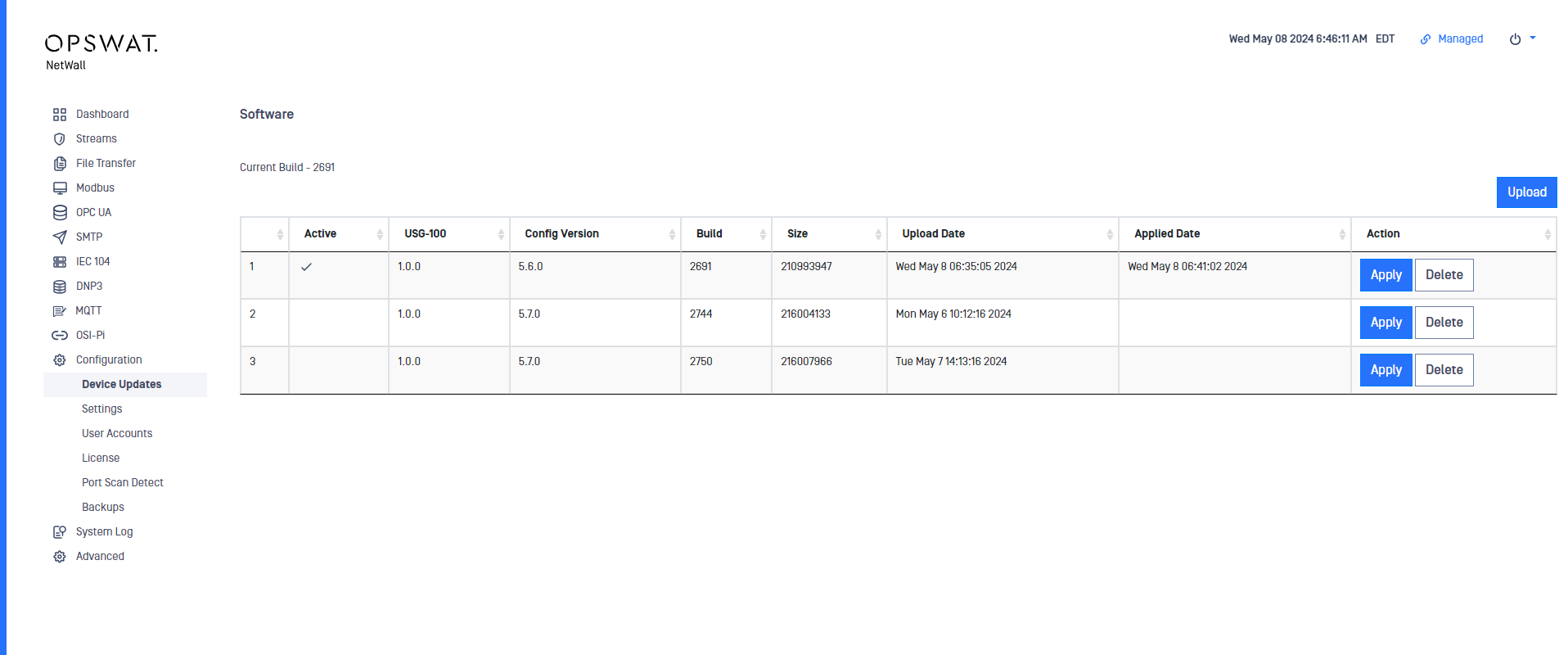
Go to Configuration-> Device Updates
Click on Upload button
Select a valid personality and click on Upload Package
Then click on Apply button, the system needs to reboot to apply the personality, continue by clicking on Apply and Reboot
TCP/UDP Streaming
You need a security dongle inserted in the server which configuration you want to change, RED or BLUE.
Prerequisites
Before you configure any transfer parameters:
This should be configured in both sides BLUE and RED. Each of the sides have their own management UI.
Ensure NetWall USG-100 BLUE and NetWall USG-100 RED network addresses are configured.
Ensure the current license and personality are uploaded.
This should be configured in both sides BLUE and RED. Each of the sides have their own management UI.
BLUE side configuration
Go to the management UI and insert user and password to login.
Click the Streams link and then click on the Action button to deploy the Action menu, then select Add Stream.
Complete the following:
Channel: You have to choose one channel number.
This channel number needs to be the same in the RED side.
Type: Type of stream being tracked. In NetWall USG-100, Unilateral is the only option available
Name: Name of the stream
Protocol: select TCP or UDP depending on the stream you want to create.
Source port: Port number of the source IP.
Source addresses: IP address(es) in the BLUE zone where the stream will originate. If you are entering more than one address, separate the addresses with a semicolon.
Enabled: checkbox to enable/disable the stream.
Max Sessions: Maximum number of sessions for the stream.
Description: user-friendly description.
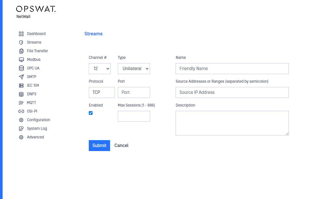
After filling in the fields, click on the Submit button to save configuration.
RED side configuration
Go to the management UI and insert user and password to login.
Click the Streams link and then click on the Action button to deploy the Action menu, then select Add Stream.
Complete the following:
Channel: You have to choose one channel number.
This channel number needs to be the same in the BLUE side.
Type: Type of stream being tracked. In NetWall USG-100 Unilateral is the only option available
Name: Name of the stream
Protocol: Select TCP or UDP depending on the stream you want to create. It needs to match with the protocol configured in BLUE side
Destination port: Port number of the destination IP.
Destination address: IP address in the RED zone where the stream will terminate. You can enter only one address.
Max Sessions: Maximum number of sessions for the stream.
Enabled: checkbox to enable/disable the stream.
Description: user-friendly description.
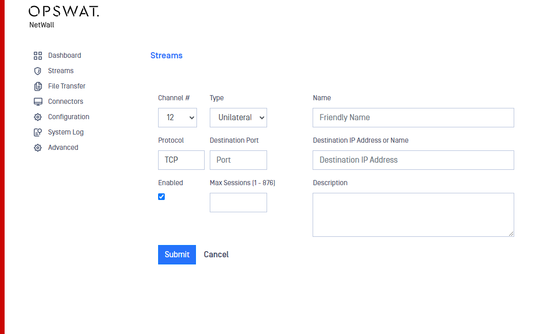
After filling in the fields, click on the Submit button to save configuration.
Modify a stream
In the Streams section, click on the stream you want to modify and the Edit Stream menu will be displayed. Modify the Stream and Submit changes.