
Network Topology
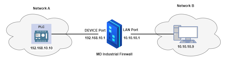
Devices Involved: A PLC (acting as a server), Industrial Firewall, and clients on Network B.
Setup:
Network A: 192.168.10.0/24 (PLC resides here).
Network B: 10.10.10.0/24 (HMI or external device).
The firewall has interfaces in both networks and translates traffic between them.
Benefit
Secure Cross-Network Access:
The PLC remains hidden from direct client access, reducing attack surfaces.
Communication occurs through the firewall.
Compatibility:
Allows legacy PLCs to communicate with modern devices on separate networks without altering their configurations.
Practical Use Cases:
A client application in Network B can fetch data or issue commands to the PLC securely.
PLC data can be monitored without exposing it to the entire client network.
Configuration Steps
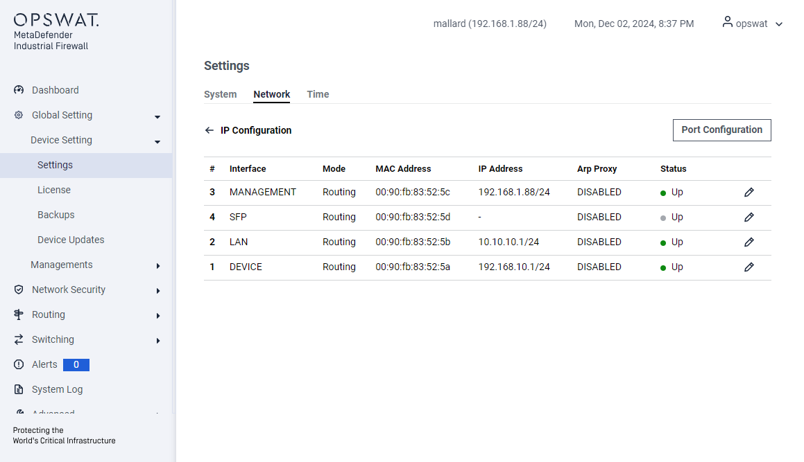
Configure the IP for the LAN and DEVICE ports:
NAT Setting
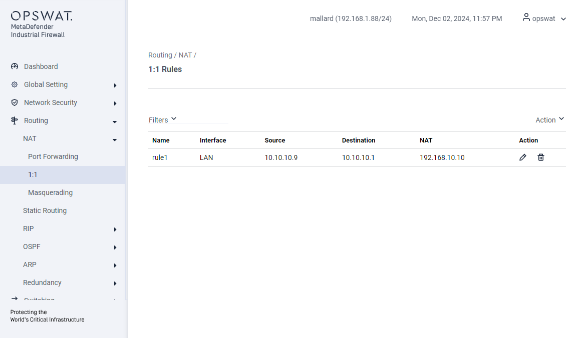
Destination NAT (1:1 or Port Forwarding):
Create rules to forward client requests to the PLC’s IP on LAN interface.
Traffic from 10.10.10.9 destined for 10.10.10.1 (firewall IP in Network B) → 192.168.10.10 (PLC’s IP address)
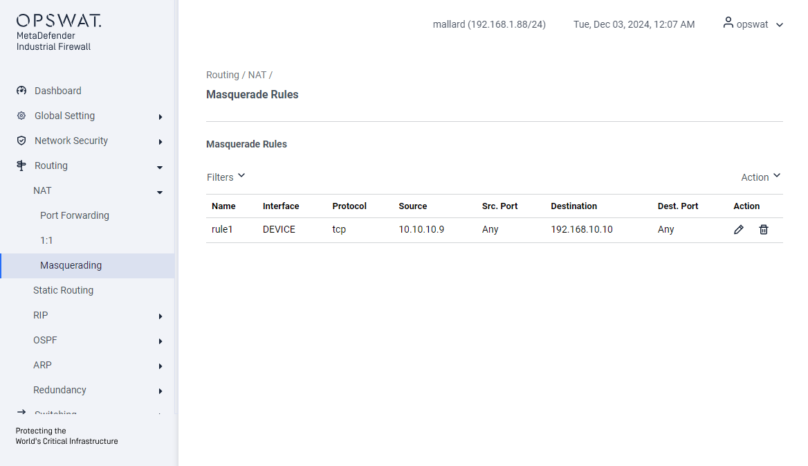
Source NAT (Masquerading):
Create Masquerading rules to translate the source IP of packets from Network B to the firewall’s IP in Network A on DEVICE interface.
Traffic from 10.10.10.9 will be translated to 192.168.10.1 (firewall IP in Network B) (DEVICE’s port)
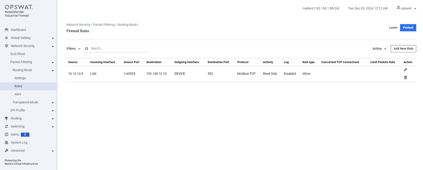
Firewall Rule
Create a rule based on the IP address after DNAT.
The initial connection is: 10.10.10.9 → 10.10.10.1
After DNAT, the connection will be: 10.10.10.9 → 192.168.10.10
PCAP Analyze
Traffic that is captured from 10.10.10.9

Traffic that is captured from 192.168.10.10
