Title
Create new category
Edit page index title
Edit category
Edit link
Routing
Virtual IPs
[Routing > Virtual IPs]
The Virtual IPs page allows you to configure additional IP addresses on a selected interface. Virtual IPs are commonly used to support gateway redundancy (e.g. VRRP), NAT, or multiple subnets on the same physical interface.__
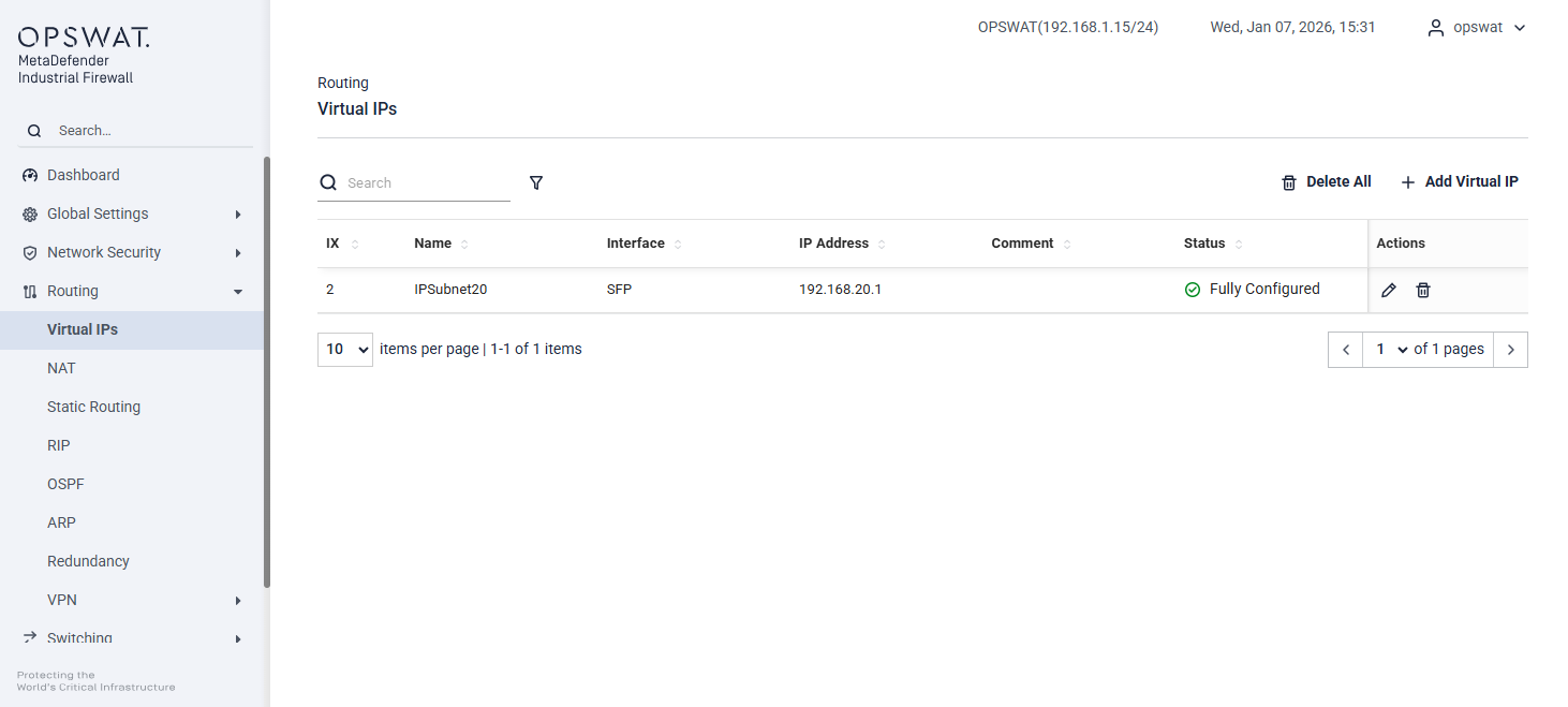
This page displays a list of configured Virtual IPs with the following information:
Name: User-defined name for the Virtual IP
Interface: Network interface on which the Virtual IP is assigned (e.g. LAN, SFP)
IP Address: The Virtual IP address
Comment: Optional description or purpose
Status: Configuration status of the Virtual IP
- Not Configured: The Virtual IP entry has been created, but no Virtual IP addresses have been added.
- Partially Configured: Some Virtual IP addresses have been added, but one or more Virtual IPs are still missing.
- Fully Configured: All required Virtual IP addresses have been added successfully.
Actions: Edit or delete the Virtual IP
Adding a Virtual IP
Click Add Virtual IP. Configure the following fields:
- Name: Enter a unique name for the Virtual IP.
- IP Address: Enter the IP address to be used as the Virtual IP.
- Interface: Select the interface to bind the Virtual IP to.
- Comment (optional): Add a description for identification.
Click Create to apply the configuration. Then the Virtual IP becomes active on the selected interface.
NAT
[Routing > NAT]
Network Address Translation (NAT) involves processes that automatically modify the IP address information within data packets. When configured on the device, NAT enables communication between devices across different networks.
Note – Each NAT rule must have a corresponding firewall rule to ensure traffic can pass through the appliance correctly.
Port Forwarding
[Routing > NAT > Port Forwarding]
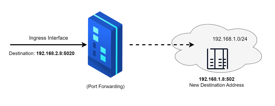
Port forwarding is used to conceal the internal network structure while still permitting external communication to reach specific devices within the network.

Name: Enter the desired name for the NAT rule.
Interface: Select the ingress interface (e.g., LAN, DEVICE) where the traffic will enter.
Protocol: Choose the protocol (e.g., TCP, UDP) for the rule.
Source: Specify the source IP address.
Source Port: Enter the source port number.
Destination IP: Provide the destination IP address. This should be the address of the ingress interface.
Destination Port: Enter the destination port number.
NAT IP: Specify the NAT IP address to which the traffic will be translated.
NAT Port: Enter the NAT port number to which the traffic will be translated.
Action: Choose whether to edit or delete the rule.
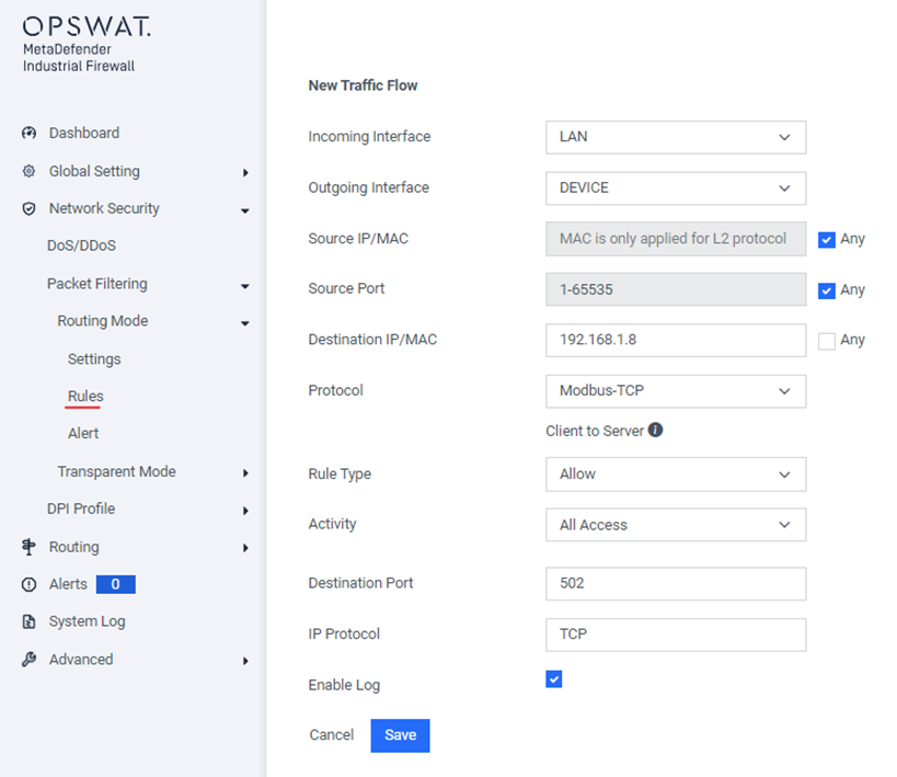
The corresponding firewall rule for this NAT rule should be added is:
1:1
[Routing > NAT > 1:1]
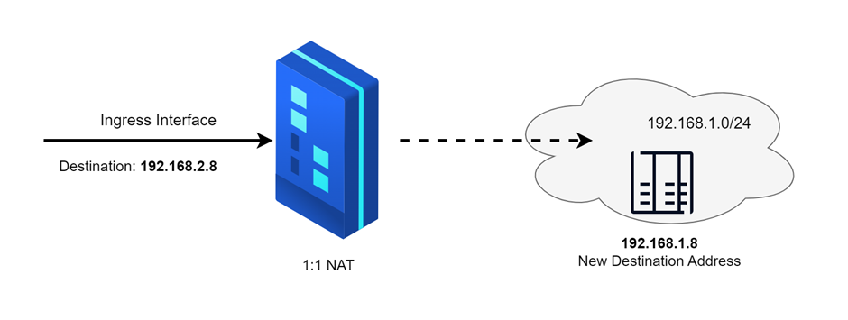
1:1 NAT (One-to-One Network Address Translation) is a networking technique where each private IP address is mapped to a single public IP address. In this scenario, there is a direct correspondence between internal and external IP addresses, with no translation of port numbers.
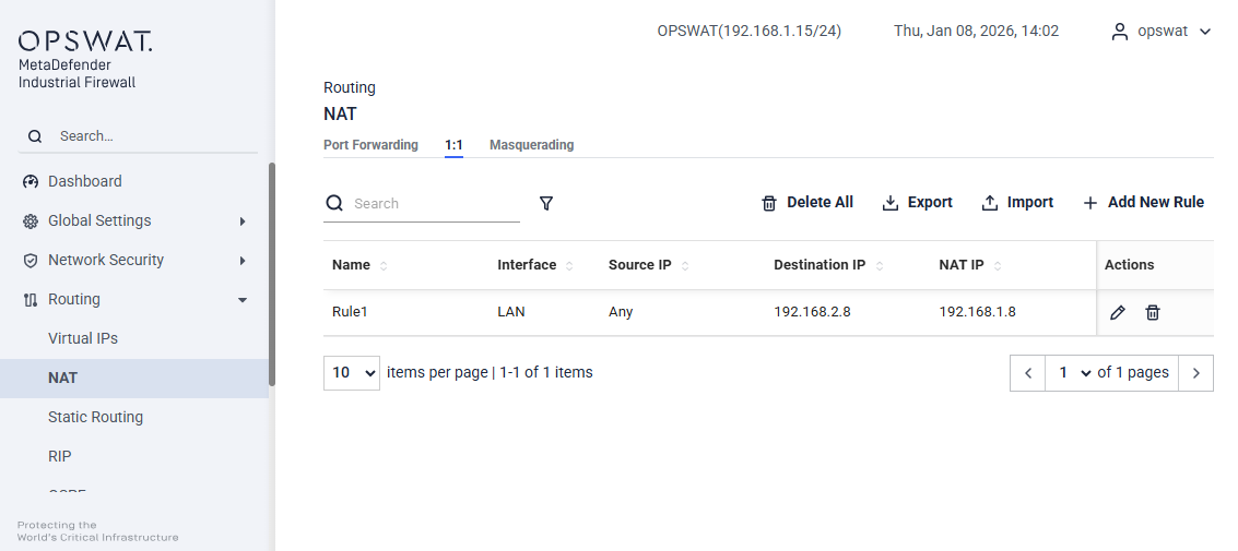
Name: Enter the desired name for the NAT rule.
Interface: Select the ingress interface (e.g., LAN, DEVICE) where the traffic will enter.
Protocol: Choose the protocol (e.g., TCP, UDP) for the rule.
Source IP: Specify the source IP address.
Destination IP: Provide the destination IP address. This should be the address of the ingress interface.
NAT IP: Specify the NAT IP address to which the traffic will be translated.
Action: Choose whether to edit or delete the rule.
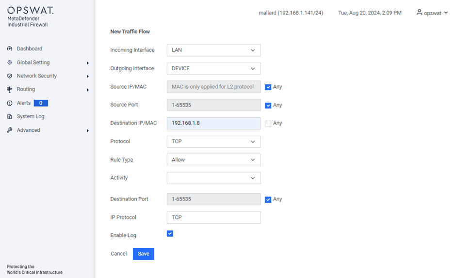
The corresponding firewall rule for this NAT rule should be added is:
Masquerading
[Routing > NAT > Masquerading]

The Masquerading NAT function conceals multiple devices behind the appliance’s IP address, effectively hiding the network’s structure from external networks. It achieves this by replacing the sender’s address in the data packet with its own IP address. Additionally, the NAT router substitutes the source port in the data packet with its own value, ensuring that response data packets are correctly routed back to the original sender.
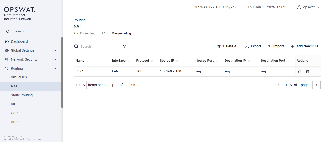
Name: Enter the desired name for the NAT rule.
Interface: Select the egress interface (e.g., LAN, DEVICE) where the traffic will go out.
Protocol: Choose the protocol (e.g., TCP, UDP) for the rule.
Source: Specify the source IP address.
Source Port: Enter the source port number.
Destination IP: Provide the destination IP address. This should be the address of the ingress interface.
Destination Port: Enter the destination port number.
Action: Choose whether to edit or delete the rule.
Static Routing
[Routing > Static Routing]
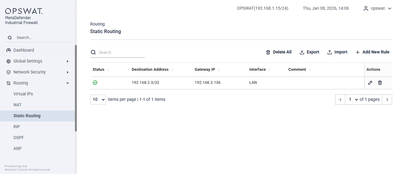
Destination Address: The IP address or network that the static route will direct the traffic.
Gateway IP: The IP address of the next hop router or gateway through which the traffic will be forwarded.
Interface: The network interface (e.g., LAN, DEVICE) through which the traffic will be sent.
Comment: An optional field to add notes or descriptions about the route for administrative purposes.
Status: Indicates whether the route is currently enabled or disabled.
Action: Choose whether to edit or delete the rule.
RIP
Setting
[Routing > RIP > Setting]
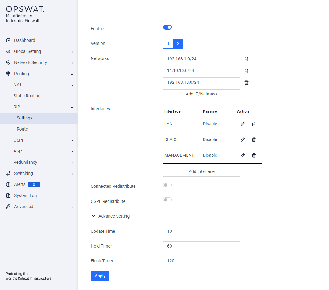
Enable: Toggle to enable or disable RIP functionality.
Version: Select the RIP version (v1 or v2) depending on the network requirement.
Networks: Specify the IP networks to advertise through RIP.
Interfaces: Choose the interfaces where RIP should operate.
Connected Redistribute: Enable to redistribute static routes into RIP.
OSPF Redistribute: Enable to redistribute OSPF-learned routes into RIP.
Advance Setting:
- Update Time: Interval for RIP route updates (default: 10 seconds).
- Hold Timer: Time to mark a route as inactive before it’s removed (default: 60 seconds).
- Flush Timer: Time to completely remove an inactive route from the routing table (default: 120 seconds).
Route
[Routing > RIP > Route]
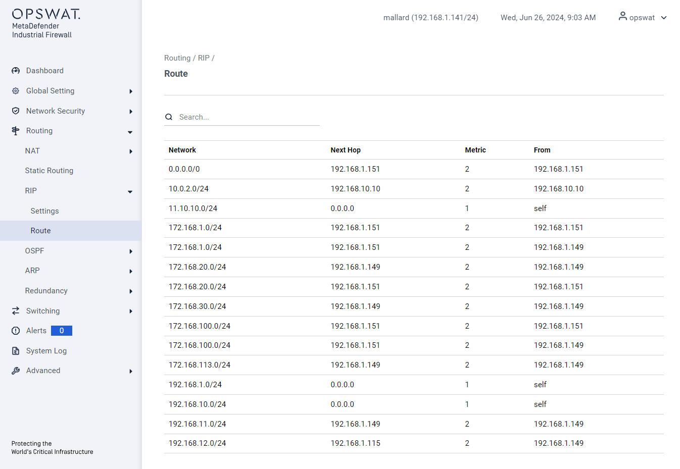
Network: The destination subnet for which the route is applied to.
Next Hop: The IP address of the next device to which packets should be forwarded.
Metric: A value that determines the route’s priority, with lower values being preferred.
From: The source of the route helps identify how the route was added to the routing table.
OSPF
Setting
[Routing > OSPF > Setting]
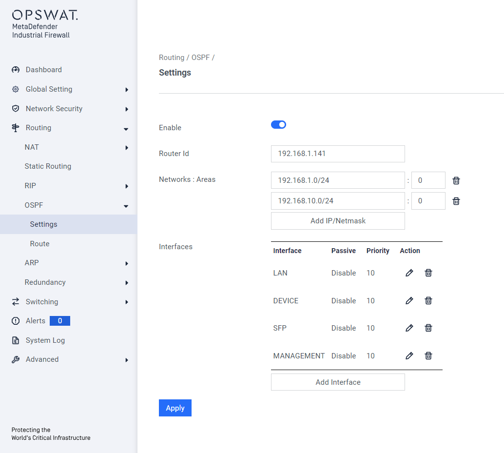
Enable: Toggle to enable or disable RIP functionality.
Router ID: A unique identifier for the router in the OSPF domain (usually an IP address).
Networks: Subnets advertised by OSPF.
Areas: Logical OSPF partitions for scalability and control (e.g., backbone area 0).
Interfaces: Physical or virtual interfaces used for OSPF communication.
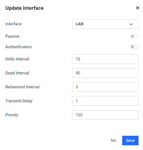
- Passive: Prevents sending OSPF Hello packets on the interface while still advertising its network.
- Authentication: Secures OSPF communication with a password or cryptographic key.
- Hello Interval: Frequency (in seconds) of Hello packet transmission.
- Dead Interval: Time (in seconds) to declare a neighbor down if no Hello packets are received.
- Retransmit Interval: Time between retransmitting OSPF Link-State Advertisements (LSAs).
- Transmit Delay: Delay (in seconds) added to LSAs before transmission.
- Priority: Determines the likelihood of an interface becoming the Designated Router (DR).
Route
[Routing > OSPF > Route]
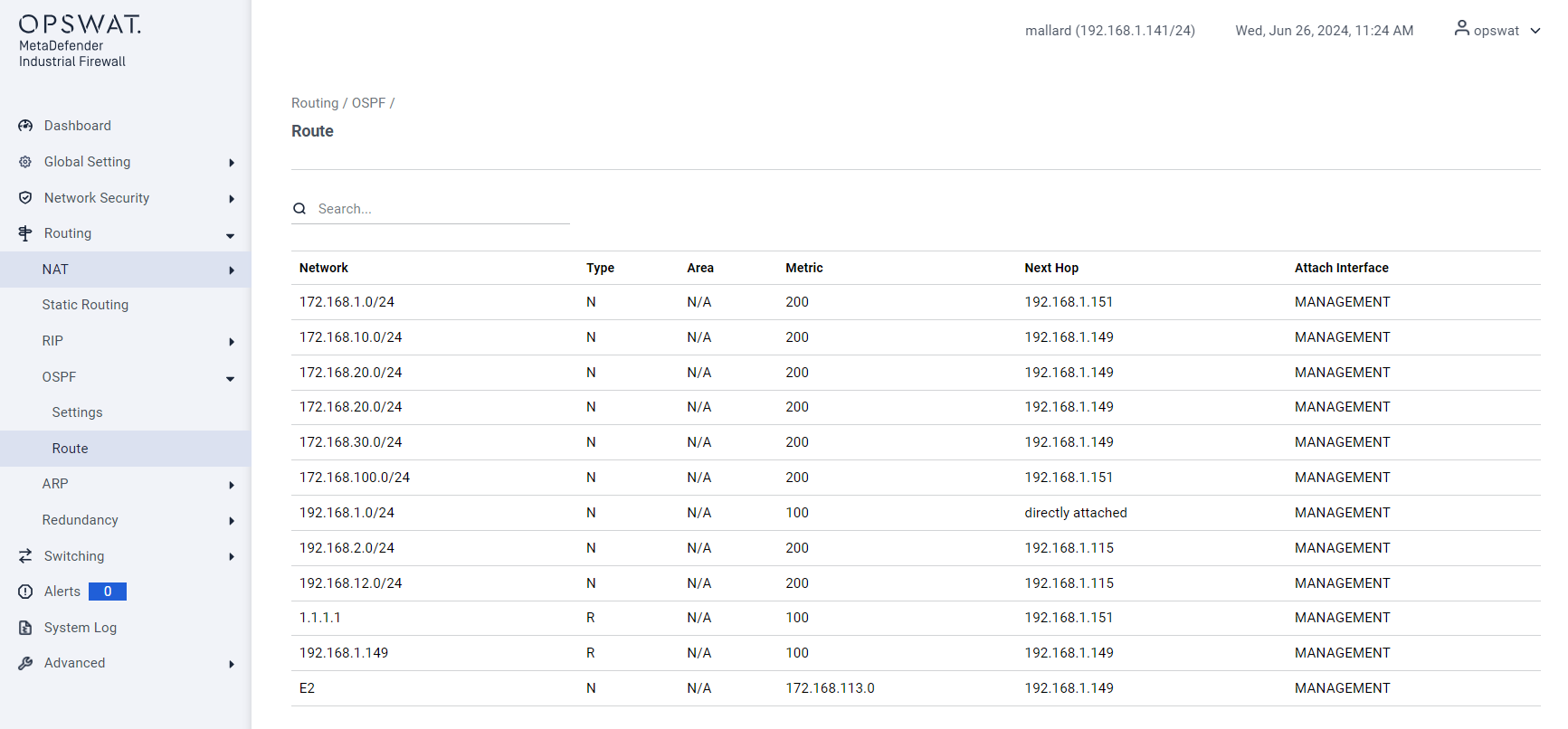
- Network: The destination network address.
- Type: The type of OSPF route
- Area: The OSPF area ID where the route was learned.
- Metric: The cost associated with the route.
- Next Hop: The IP address of the next hop router.
- Attach Interface: The interface through which the next hop is reachable.
ARP
Setting
[Routing > ARP > Setting]
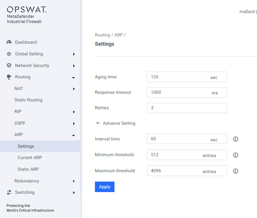
- Aging Time: Duration (in seconds) an ARP entry remains in the cache before being removed.
- Response Timeout: Time to wait for an ARP reply before considering the request failed.
- Retries: Number of attempts to resend an ARP request if no reply is received.
- Interval Time: Delay between retries for ARP requests.
- Minimum Threshold: Minimum number of ARP entries allowed in the cache before action is taken.
- Maximum Threshold: Maximum number of ARP entries allowed in the cache.
Current ARP
[Routing > Current ARP > Setting]
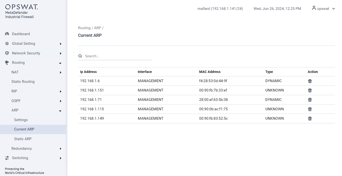
- IP Address: The IP address associated with the ARP entry.
- Interface: The network interface corresponding to the ARP entry.
- MAC Address: The MAC address mapped to the IP address.
- Type: Entry type (e.g., static or dynamic).
- Action: Option to delete the ARP entry.
Static ARP
[Routing > Static ARP > Setting]
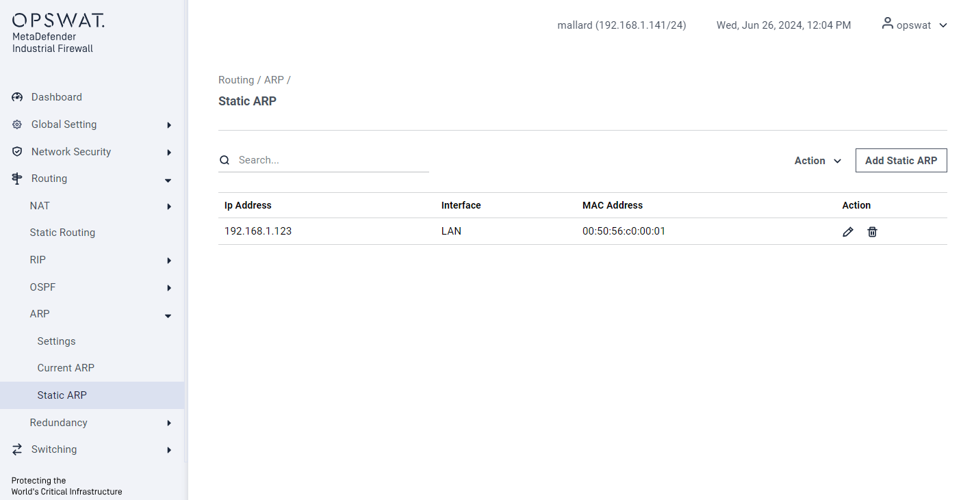
- Add Static ARP: Manually create an ARP mapping.
- IP Address: The IP address to be mapped.
- Interface: The interface associated with the static ARP entry.
- MAC Address: The MAC address mapped to the specified IP address.
- Action: Edit or Remove the static ARP entry.
VPN
IPSec
[Routing > VPN > IPSec]
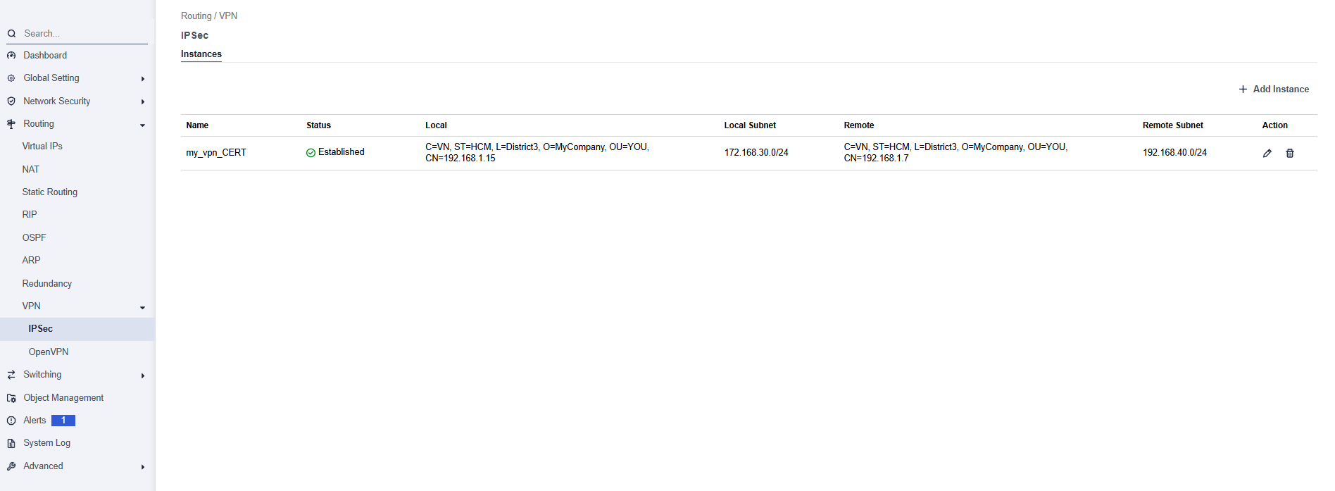
This page allows to configure and manage IPSec VPN tunnels between the OPSWAT Industrial Firewall and remote peers to securely connect separate network segments.
- Name: The name of the VPN instance (user-defined).
- Status: Displays the current connection status.
- Local: The local firewall’s identity details from certificate page (Certificates).
- Local Subnet: The subnet behind the local firewall.
- Remote: The remote peer’s identity details.
- Remote Subnet: The subnet behind the remote peer included in the VPN.
- Action:
- Edit Icon – Modify the VPN settings.
- Delete – Remove this VPN instance.
Add Instance
Section: General Configuration
- Connection Name: Unique name for the IPSec connection
- Key Exchange Protocol: Choose between IKEv1 or IKEv2, depending on compatibility and features.
- Authentication Method: Select PSK (Pre-Shared Key) or Certs (Certificate-based authentication).
- VPN Type: Policy Base or Route Base
Section: Local Gateway
- Local WAN IP: Public or external IP of the local firewall.
- Local Subnet: Internal network to be routed over the VPN
- Local Identifier:
- Policy Base: Use any descriptive string
- Route Base: Use the certificate subject name (e.g., CN=vpn.localdomain.com)
Section: Remote Gateway
- Remote WAN IP: IP address of the remote VPN peer
- Remote Subnet: Remote network to route through the VPN
- Remote Identifier: Identity of the remote gateway (certificate subject)
Section: Authentication
Policy Base:
- Pre-Shared Key: Enter the pre-shared key. This key must match on both ends of the VPN tunnel.
Route Base:
- Local Certificate: Select from pre-uploaded or generated certificates for authentication.
- CA Certificate: Certificate Authority (CA) used to validate the remote peer’s certificate.
Section: Encryption Settings
- Add Proposals: Choose an encryption algorithm for the IKE phase.
- Diffie-Hellman Group: The group for key exchange.
Section: Firewall Rules & Policy
- Allow UDP 500: Enables IKE negotiation over UDP port 500 (default, required).
- Allow UDP 4500: Enables NAT Traversal (optional, but recommended if NAT is used).
- Allow ESP: Enables Encapsulated Security Payload (ESP) for IPSec traffic.
- Encapsulation: Optional: Select encapsulation mode if required.
OpenVPN
[Routing > VPN > OpenVPN]
This page allows you to configure and manage OpenVPN server instances on your firewall. OpenVPN is a flexible and secure solution for creating encrypted tunnels, commonly used for remote access (allowing individual users to connect to the network) and site-to-site connections.
The page is divided into two main tabs:
- Server: For configuring instances where the firewall acts as an OpenVPN server, accepting connections from clients.
- Client: For configuring instances where the firewall acts as an OpenVPN client, connecting to a remote OpenVPN server.
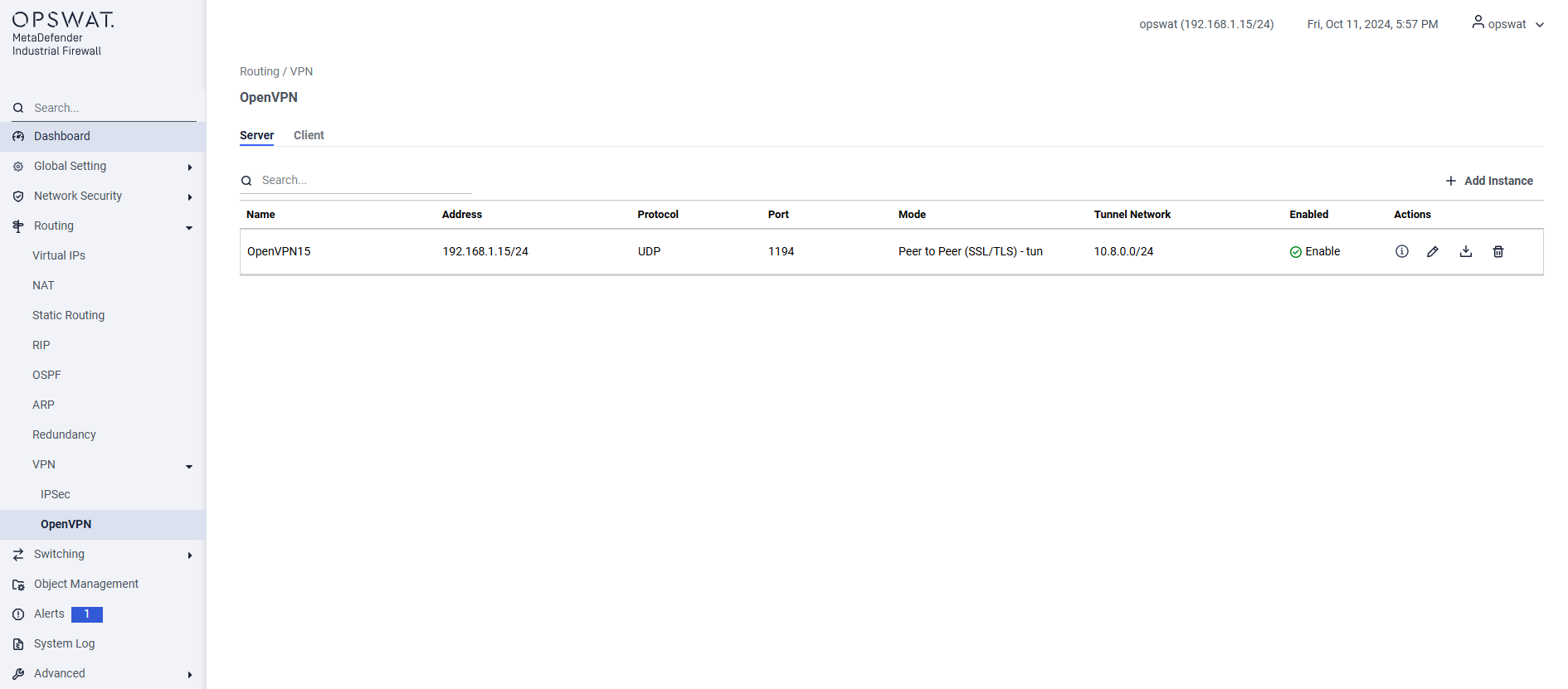
- Name: A unique, user-defined name for the VPN instance (e.g., OpenVPN15).
- Address: The IP address and subnet of the firewall's interface that will listen for incoming VPN connections.
- Protocol: The transport protocol used for the VPN tunnel (UDP or TCP). UDP is generally faster and preferred.
- Port: The port number the server will listen on (default is 1194).
- Mode: The authentication and topology mode. Peer to Peer (SSL/TLS) is a common mode that uses certificates for secure authentication.
- Tunnel Network: The virtual IP address pool that will be assigned to connecting clients (e.g., 10.8.0.0/24).
- Enabled: Shows whether the server instance is currently active.
Add Instance
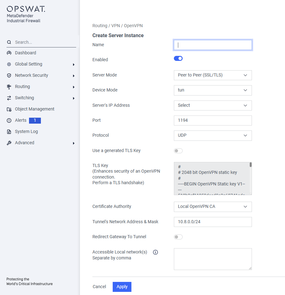
Basic Configuration
- Name: Enter a unique, descriptive name for this VPN server instance
- Enabled Use this toggle switch to activate or deactivate the server instance after it has been configured.
Server Settings
Server Mode Select the operational mode for the VPN.
Peer to Peer (SSL/TLS)is a highly secure mode that requires both the server and each connecting client to use digital certificates to authenticate each other.Device Mode:
- tun (Tunnel): This is the most common mode. It creates a routed, Layer 3 IP tunnel. Use this for standard remote access.
Server's IP Address Select the IP address of the firewall interface that will listen for incoming VPN connections from the internet or an untrusted network.
Port Enter the port number the server will listen on. The default and standard port for OpenVPN is 1194
Protocol Choose the transport protocol for the VPN tunnel.
- UDP: Faster and generally recommended for VPNs.
- TCP: Slower but more reliable; use this only if UDP is blocked on the network.
Security Settings
- Use a generated TLS Key: Enable this to add an extra layer of security. A TLS Authentication key provides HMAC signature verification on top of the standard TLS handshake, protecting against DoS attacks and port scanning.
- TLS Key: If the option above is enabled, this field will display the generated pre-shared static key.
- Certificate Authority: Select the Certificate Authority (CA) that will be used to sign and validate client certificates. All clients attempting to connect must present a certificate signed by this CA.
Network Settings
- Tunnel's Network Address & Mask: Define the virtual IP network that will be used for the VPN. Connecting clients will be assigned an IP address from this range (e.g.,
10.8.0.0/24). This network must be unique and not overlap with any of your existing local networks. - Redirect Gateway To Tunnel Enable this option to create a "full tunnel". When a client connects, all of its internet traffic will be forced through the VPN. This is useful for ensuring all traffic from a remote device is inspected by the firewall.
- Accessible Local network(s) If Redirect Gateway is disabled, use this field to create a "split tunnel". Enter the local network subnets (e.g.,
192.168.1.0/24) that you want remote clients to be able to access.
Saving the Instance
- Cancel: Discards your changes and returns to the previous page.
- Apply: Saves and creates the new OpenVPN server instance. You will still need to ensure the "Enabled" toggle is on for it to start accepting connections.

