Network Topology
Devices Involved: A PLC (acting as a server), Industrial Firewall, and clients on Network B.
Setup:
- Network A: 192.168.10.0/24 (PLC resides here).
- Network B: 10.10.10.0/24 (HMI or external device).
- The firewall has interfaces in both networks and translates traffic between them.

Benefit
Secure Cross-Network Access:
- The PLC remains hidden from direct client access, reducing attack surfaces.
- Communication occurs through the firewall.
Compatibility:
- Allows legacy PLCs to communicate with modern devices on separate networks without altering their configurations.
Practical Use Cases:
- A client application in Network B can fetch data or issue commands to the PLC securely.
- PLC data can be monitored without exposing it to the entire client network.
Configuration Steps
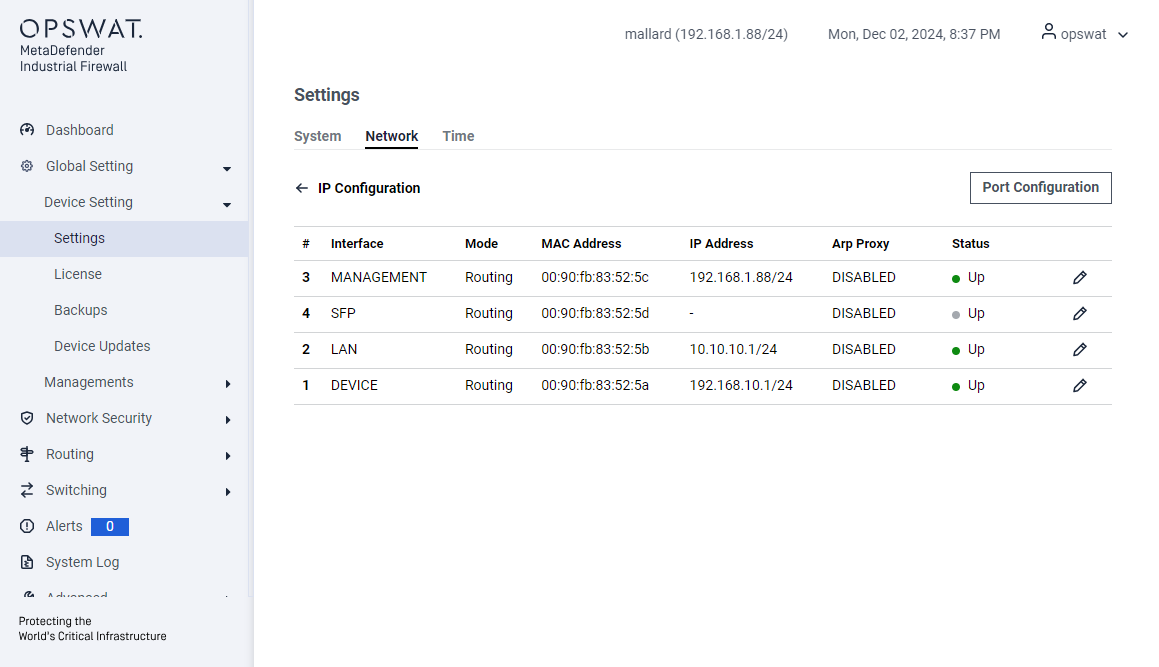
Configure the IP for the LAN and DEVICE ports:

NAT Setting
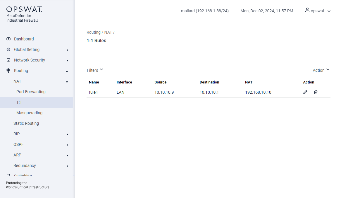
Destination NAT (1:1 or Port Forwarding):
- Create rules to forward client requests to the PLC’s IP on LAN interface.
- Traffic from 10.10.10.9 destined for 10.10.10.1 (firewall IP in Network B) → 192.168.10.10 (PLC’s IP address)

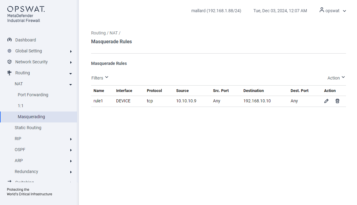
Source NAT (Masquerading):
- Create Masquerading rules to translate the source IP of packets from Network B to the firewall’s IP in Network A on DEVICE interface.
- Traffic from 10.10.10.9 will be translated to 192.168.10.1 (firewall IP in Network B) (DEVICE’s port)

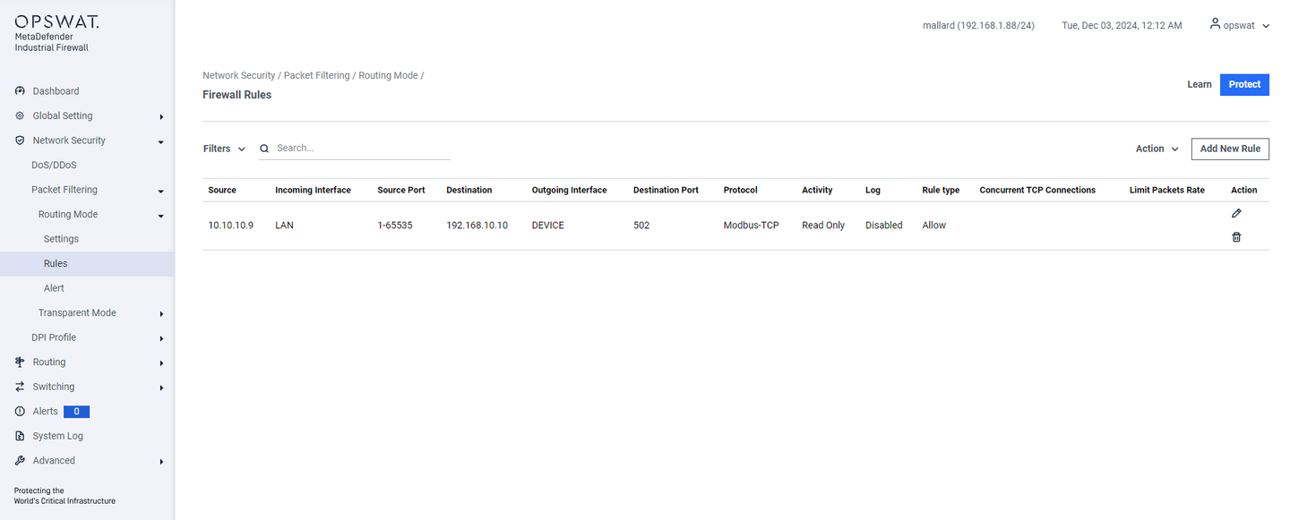
Firewall Rule
Create a rule based on the IP address after DNAT.
- The initial connection is: 10.10.10.9 → 10.10.10.1
- After DNAT, the connection will be: 10.10.10.9 → 192.168.10.10

PCAP Analyze
Traffic that is captured from 10.10.10.9

Traffic that is captured from 192.168.10.10


