About this task
Use this procedure for Network Sensor Configuration Login and Network Configuration for the Network Sensor on the local management console application
Before you begin
Ensure that you completed the installation for the Network Sensor on local management console application.
Prepare display screen, keyboard, and mouse physically attached to the Network Sensor server to serve during the configuration process
Procedure
After installation, the MetaDefender OT Security Network Sensor on the local management console application is starting
Network Sensor Configuration Login
1. Login with the default username/password
Steps:
- Input username and password for the admin default user
- Click Login
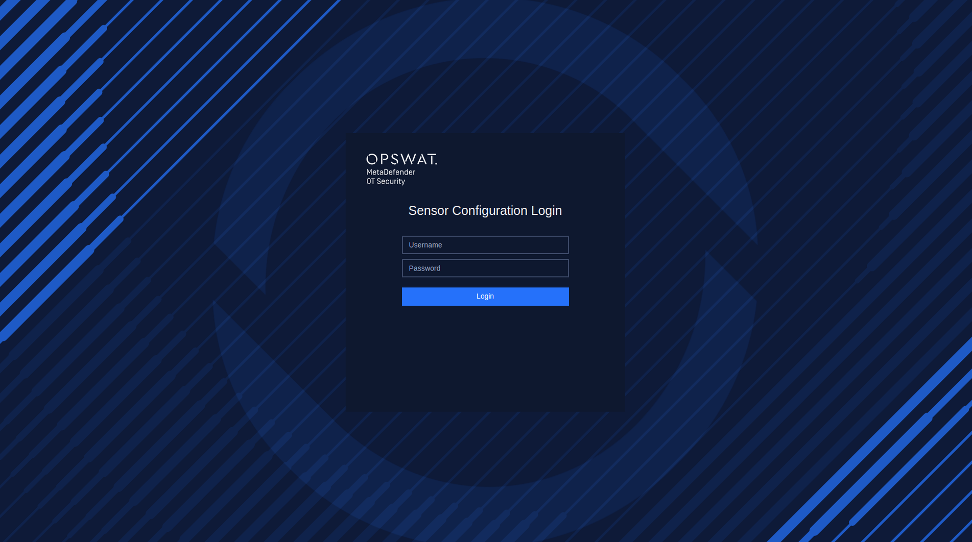
Login with the credentials default
2. Reset the password on the first login
After successfully logging in with the default username and password, it is necessary to reset the password. Steps:
- Input new password
- Input to confirm new password
- Click Submit
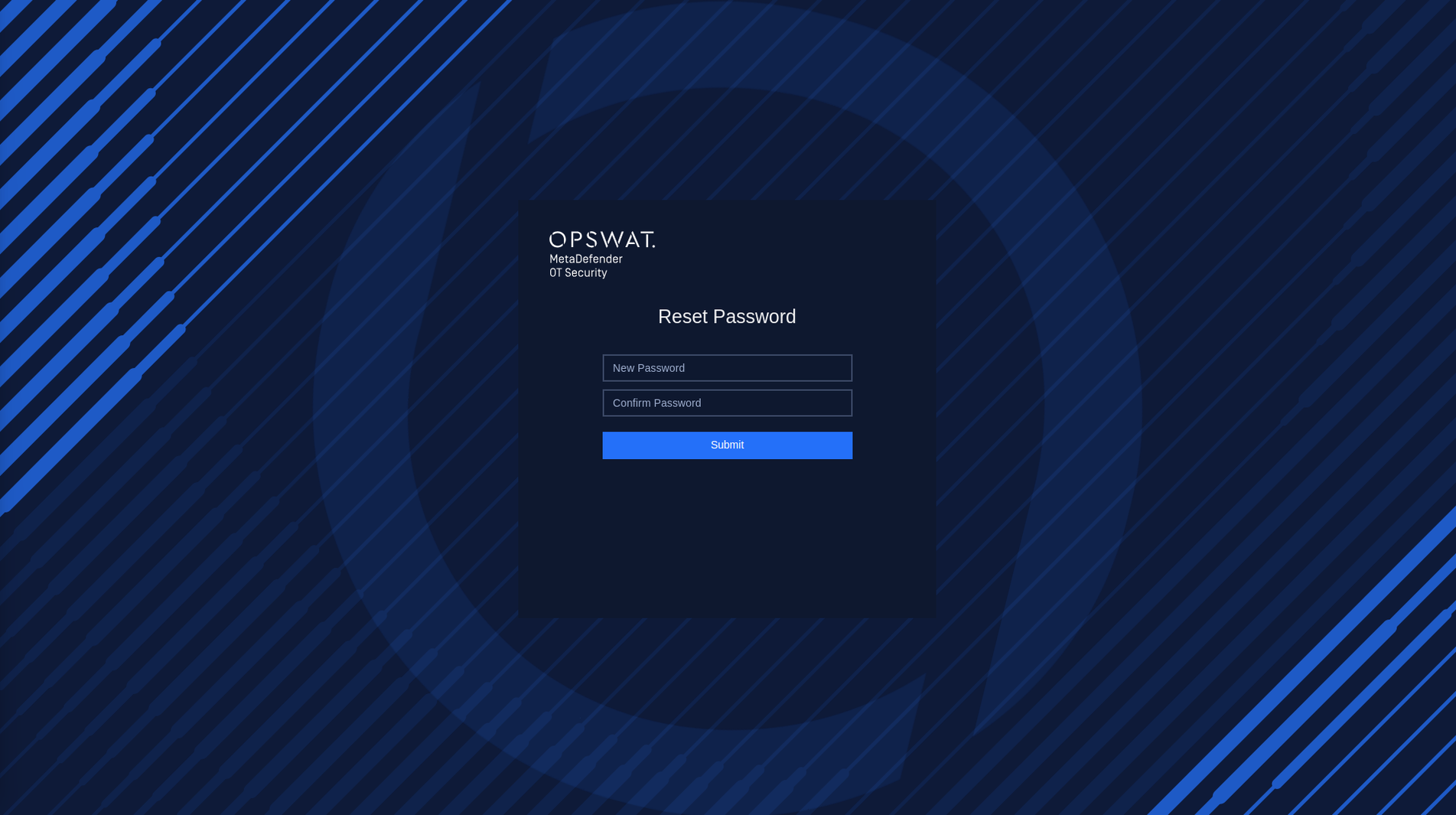
Reset Password
Network Sensor Network Settings
Overview Network Sensor Network Setting
1. Checking Network Interface
During this step, our application will detect the Network Interface Cards (NICs) that are currently plugged into your computer. This allows our application to determine which NICs are available for use with our software.
If you have multiple NICs connected to your computer (such as a Built-in NIC, USB NIC 1, and USB NIC 2), our application will display all available NICs on the screen. To help you identify which port each NIC is connected to, you can unplug the cable and the status of the NIC will be changed to "Unavailable" in our application.
If our application fails to detect all of your available NICs, you can click the "Recheck" button in the top right corner of the screen to rescan for all NICs.

Recheck button
To use an NIC with our software, toggle the button next to its name. You can disable NICs you don't want to use.

Enable/Disable Network Interface
Click on the Save button to save the changes.
2. Select NIC using for Site connectivity and scanning
2.1. Select NIC using for Site connectivity
The purpose of this is to select a specific NIC for connecting between the Network Sensor and the Site Manager.
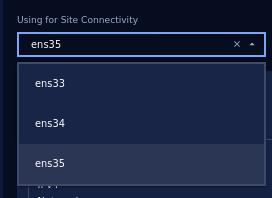
Select NIC using for Site Connectivity
2.2. Select NIC using for scanning
You can set up discovery settings for each NIC by selecting either "Passive discovery" or "Smart active discovery". The system will do the scanning based on the network configuration for NICs that you set up (for both active and passive scanning). Particularly:
- Passive discovery: This setting allows the NIC to receive packets from Switch. This is useful for monitoring network traffic without disrupting it. Passive discovery requires the selected NIC to be connected to the SPAN (mirror) port of the switch. We recommend the users use built-in NIC for passive scanning to have better performance.
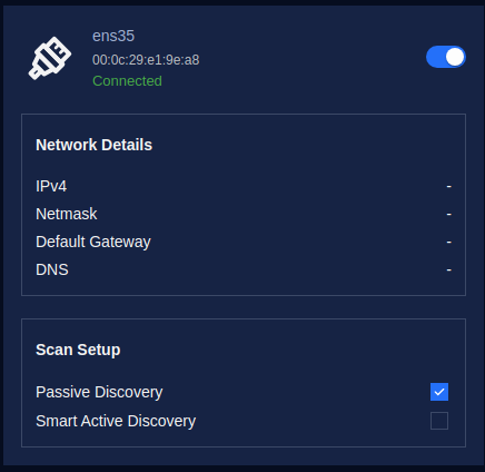
Select NIC for Passive Discovery
- Smart active discovery: This setting sends packets to probe the network and discover other devices. This is useful for identifying network topology and detecting potential issues. The NIC for Smart active discovery is recommended NOT to be connected to the SPAN (mirror) port of the switch.
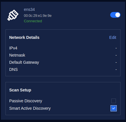
Select NIC for Active Discovery
3. Select NIC using for Patch Management
This aims to select a specific NIC for Integrated patching capabilities for firmware from Siemens vendor to streamline updates and manage vulnerabilities.
Click “Select a NIC” under “Using for Patch Management” to choose a specific NIC from the droplist. This list displays all the NICs we enabled earlier, and we only need to select one.
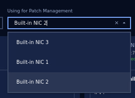
Select NIC using for Patch Management
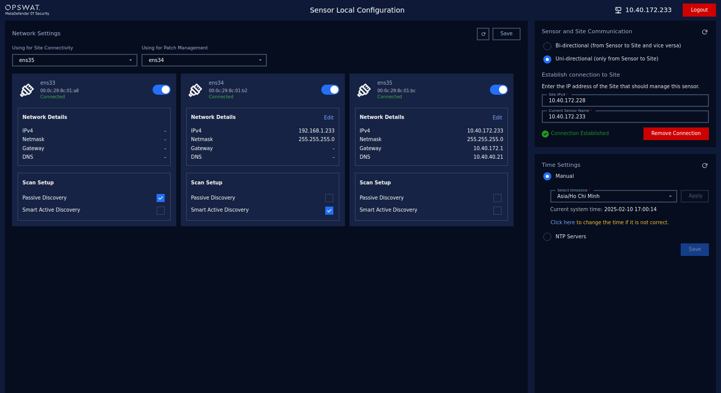
4. Configure Network Interfaces
For each NIC, you can set up the IPv4 address by selecting either "Auto (DHCP)" or manually inputting the address, netmask, and gateway. This allows you to customize the network settings to fit your specific needs.
It should be noted that:
- You need to configure IPs only for NICs selected to use as Active Discovery
- You do not need to configure the IP for the NICs used as Passive Discovery.
- MetaDefender OT Security captures only traffic from NICs that are configured as Passive Discovery or Active Discovery.
In this step, you can access and configure a list of available network interfaces (NICs). To configure a NIC, click on the “Edit” button to access the configuration options of the NIC selected in the previous step.
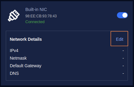
Click on the “Edit” button to access the configuration options
By default, the option is Auto (DHCP), In case your system has a DHCP server, just enter additional DNS.
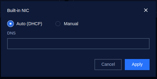
Then click the Apply button to save the changes.
For optimal performance, it is recommended to use static IP addresses. Therefore, we should switch to Manual configuration.
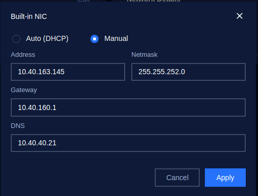
Config Manual for NIC
Please enter the required details - your address, netmask, gateway, and DNS, in the provided fields. After entering all the details, click on the "Apply" button to save the changes.
Finally, save your configuration, simply click on the Save button located at the top right corner of the screen.
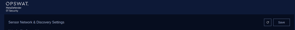
Click on the Save button to save the configuration
Click on the Save button to save the configuration
Network Connectivity - Network Sensor and Site Manager communication
Based on your organization's security rules, it's important to select the appropriate communication method for MetaDefender OT Security when setting up connectivity between the Network Sensor and the Site Manager.
*Note: Make sure to select the matching communication model between all components involved: Site Manager, Enterprise Manager, and Network Sensors. This ensures consistent and reliable communication across the system.
Model #1. Bi-directional (from Sensor to Site and vice versa)
Two-way (inbound + outbound) communications between components
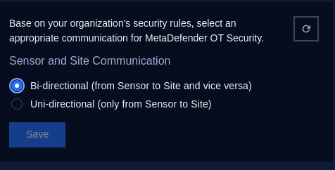
Model #2. Uni-directional (only from Sensor to Site)
One-way (outbound) communication to the upper component.
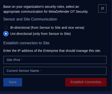
When selecting this communication method, you'll need to:
- Input the Site Manager IPv4 Address: Enter the IP address of the Site Manager to establish the connection.
- Input the Current Sensor Name: Provide the name of the sensor that corresponds to the Network Sensor.
- Save and Establish Connection: Once you've entered the required information, click on Save and Establish Connection. This action will save the configuration and add the Network Sensor to the Site Manager system.
Time Settings
Configuring the system time can be done using two methods: manual time setting and synchronizing time via an NTP (Network Time Protocol) server. You can choose the most suitable option based on your system’s requirements.
1. Manual Time Setting
In this method, users can manually set the system's time and select the appropriate timezone.
Steps to Configure Time Manually:
Click to Select Manual
Select Timezone:
- Look for the Timezone dropdown or field.
- Choose your desired time zone from the list of available options. For example, you can select Asia/ Ho Chi Minh, etc.
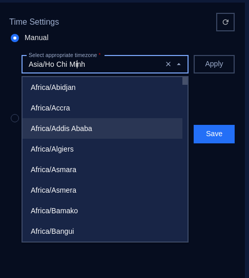
- Once you’ve entered the correct timezone, click on the Apply button to store your changes.
Manually Set the Date and Time if it is not correct.
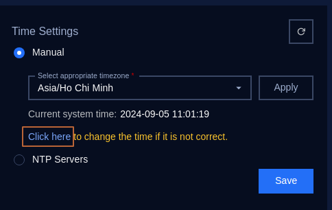
Click on “Click here” to open the Change system Time popup:
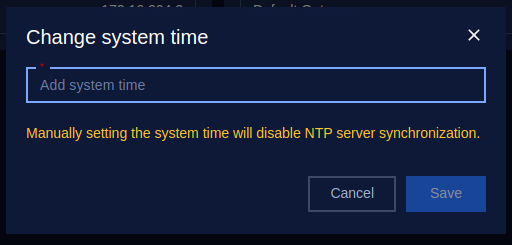
Then click “Add system time”:
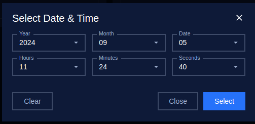
In the Date and Time fields, manually input the current date and time.
- Date Format: Typically follows YYYY-MM-DD (e.g., 2024-08-29).
- Time Format: The time format follows the pattern HH:MM:SS (e.g., 11:01:19) using the 24-hour clock format.
Save the Settings: Once you’ve entered the correct date, time, and timezone, click on the Save button to store your changes.
Verify the Changes: Ensure that the system reflects the correct date, time, and timezone on the interface.
2. NTP Servers
NTP (Network Time Protocol) is a protocol designed to synchronize the clocks of networked devices to a global standard time, usually via online servers. This method ensures that the system time is accurate and automatically updated.
Steps to Configure NTP Server:
Click to select NTP Servers:
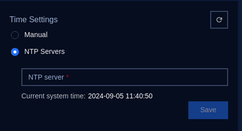
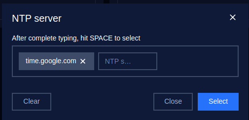
Input NTP Server Address:
You will be prompted to input an NTP server. Examples of commonly used NTP servers are:
- pool.ntp.org
- time.google.com
- time.windows.com
Enter the preferred NTP server URL or IP address into the NTP Server field.
Apply the Settings:
After entering the NTP server information, click the Save button to store the settings.
The system will now synchronize its time with the NTP server at regular intervals.
Verify NTP Synchronization:
Check the system time to ensure it matches the correct time after synchronization.