
Prerequisites
Hardware requirements
If any items you are supposed to receive are missing or damaged, contact Support.
You will receive a package from OPSWAT containing one of four hardware form factors:
One NetWall 1U Server
2 x 1U NetWall Servers
2 X 1U DELL Enterprise Servers
Accessories:
Power Cables.
Two for 1U Server
Four for 2 x 1U Servers
Fiber Optic Cables.
Two for server models
Two Security Dongles.
Mounting Rail Kit (1U Servers only)
In addition, you will need:
Flathead screwdriver.
Ethernet cables.
The installation location must provide:
Access to the USB port on the MetaDefender Optical Diode BLUE node. Ports are available on the front and back of the node.
1U or 2 x 1U rack space depending on model.
250 Watts power in the rack where the nodes will be installed.
The included power cables are intended for exclusive use with the NetWall appliance
Installation Procedure
MetaDefender Diode X installation includes the following steps:
Install the servers in the rack.
Connect the servers to your system.
Connect the servers to each other.
Power up each node.
Install Servers in the Rack
Install each server in the rack with the supplied mounting rails, following your local procedures.
The sides containing the USB ports should be toward the front of the rack. You will insert a dongle in the USB port of the MetaDefender Transfer Guard BLUE appliance.
Connect Servers to System
1U Server for 100Mbps, 1Gbps and 10Gbps
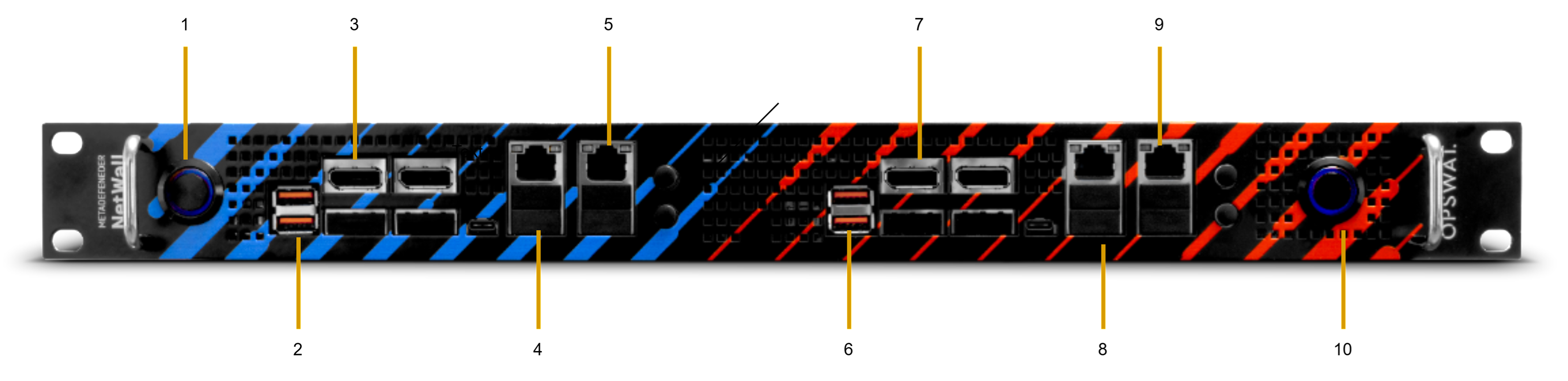
1 | Power | BLUE on/off |
2 | Security Dongle USB | Must be inserted to perform configuration changes. |
3 | Display Port | Connect monitor to access BLUE UI. |
4 | RJ45 Port (LAN1) | Optical Diode BLUE: Connect to the source network with an ethernet cable. |
5 | RJ45 LAN Port (LAN2) | BLUE Management Port. |
6 | Security Dongle USB | Must be inserted to perform configuration changes. |
7 | Display Port | Connect to monitor to access the RED UI. |
8 | RJ45 LAN Port (LAN3) | Optical Diode RED: Connect to the destination network with an ethernet cable. |
9 | RJ45 LAN Port (LAN4) | RED Management Port |
10 | Power | RED on/off |
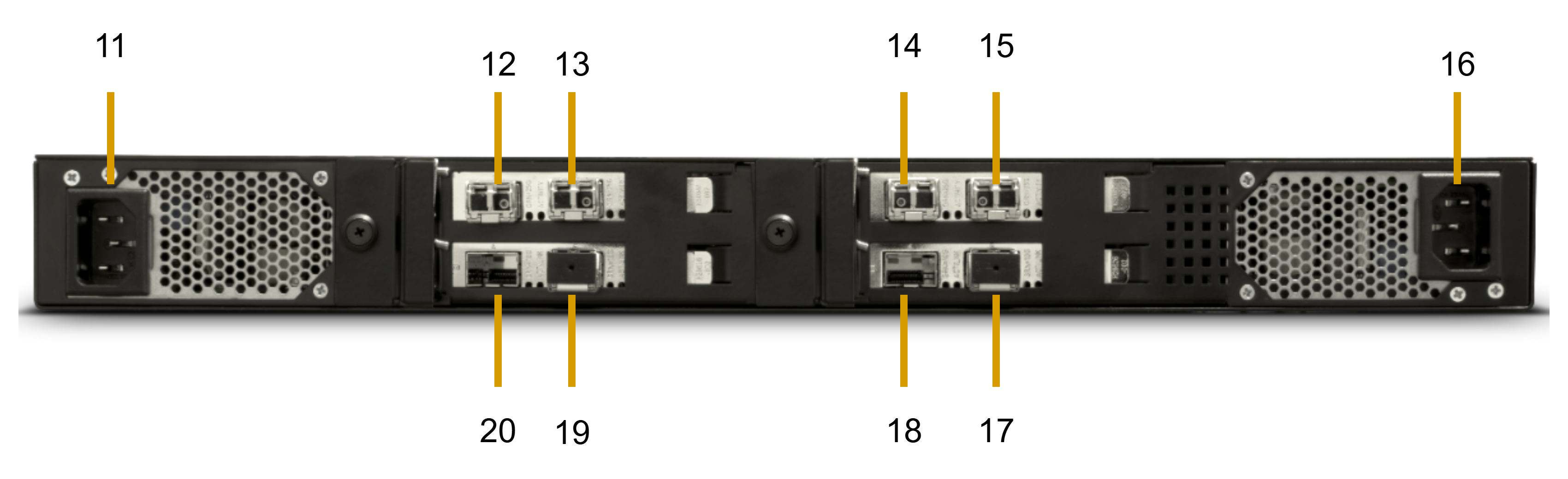
11 | Power Supply Unit (Red) | Connect Optical Diode RED to the power supply with power cable. |
12 | SFP1 Slot (RX) | Optical Diode RED: Connect the provided fiber to the SFP TX [14]. |
13 | SFP2 Slot (RX) | Optical Diode RED: Connect the second provided fiber to the SFP TX [15]. |
16 | Power Supply Unit (Blue) | Connect Optical Diode BLUE to the power supply with power cable. |
17 | 10G SFP+ [Blue] | Connect to source network with an ethernet cable. |
18 | 10G SFP+ [Blue] | Connect to source network with an ethernet cable. |
19 | 10G SFP+ [Red] | Connect to destination network with an ethernet cable. |
20 | 10G SFP+ [Red] | Connect to destination network with an ethernet cable. |
2 X 1U Servers for 100Mbps and 1Gbps
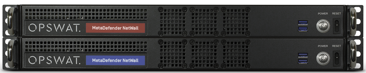
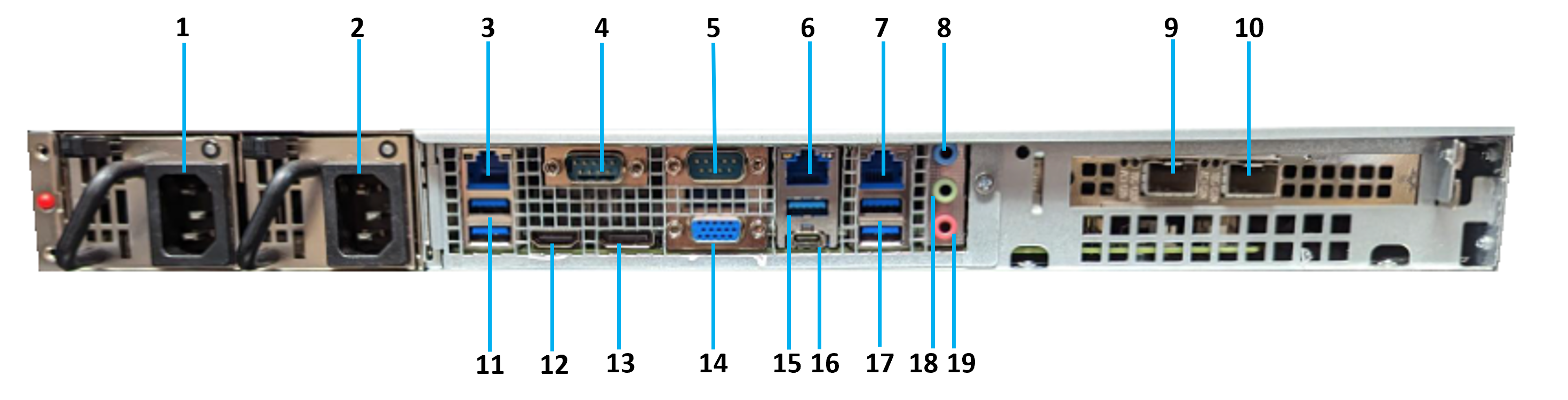
The following graphic shows the front and rear view of the server.
T
Use the following table to connect both servers to your system. You will not need all of the connections for the MetaDefender Diode X installation.
Port Number | Description | MetaDefender Diode X Connection |
|---|---|---|
1 | Power supply unit | Connect MetaDefender Diode X BLUE and RED to their power supplies with the power cables. |
2 | Redundant Power supply unit. | Connect MetaDefender Diode X BLUE and RED to their power supplies with the power cables. |
3 | RJ45 LAN Port (LAN3) | N/A |
4 | COM Port (COM1) | N/A |
5 | COM Port (COM2) | N/A |
6 | RJ45 LAN Port (LAN2) | N/A |
7 | RJ45 LAN Port (LAN1) | Optical Diode BLUE: Connect to the source network with an ethernet cable. Optical Diode RED: Connect to the destination network with an ethernet cable. |
8 | Line In | N/A |
9 | SFP1 Slot | Optical Diode BLUE: Connect the provided fiber to the SFP TX here. Optical Diode RED: Connect the other end of the provided fiber to the SFP RX here. |
10 | SFP2 Slot | Optical Diode BLUE: Connect a second provided fiber to the redundant SFP TX here. Optical Diode RED: Connect the other end of the second provided fiber to the redundant SFP RX here. |
11 | USB 3.2 Gen 2 Ports | N/A |
12 | HDMI Port (HDMI1) | Connect to a HDMI monitor to access the CLI. |
13 | DisplayPort (DP1) | N/A |
14 | D-Sub Port (VGA1) | Connect to a VGA monitor to access the CLI. |
15 | USB 3.2 Gen 2 Port | N/A |
16 | USB 3.2 Gen 2 Type-C Port | N/A |
17 | USB 3.2 Gen 2 Ports | N/A |
18 | Line Out | N/A |
19 | Microphone | N/A |
Connect servers to each other
Use the fiber optic cable to connect the servers to each other. Install each end of the simplex fiber jumper into the connector indicated by Port Number 9 in the above table as appropriate based upon server color. If redundant fiber connections are being used, connect the second simplex fiber jumper likewise into the connector indicated by Port Number 10.
Make sure both servers are powered off before connecting them. Computer cables should always use strain relief to protect the connected equipment from excessive force via the cable. This is especially important for cables between racks.
Power up Diode X Appliances
Press the power button on each MetaDefender Diode X appliance to power it up. Press each power button a second time to shut down that appliance. You also can reset the appliance pressing the other button placed to the right.
Basic Configuration via Configuration File
This feature enables basic configuration parameters to be uploaded via a JSON Configuration File. It is useful in instances whereby a user is configuring a fleet of Diode X. Most users should utilize configuration instructions in the Configuration section of the manual. The feature supports configuring TCP, UDP, HTTPs and Syslog. Other connectors must be configured manually.
Config via Configuration File BLUE
This functionality only works for an initial setup when no Management IP/device has been previously configured.
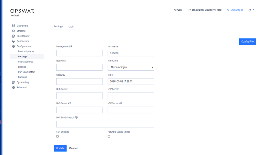
Log in and accept the EULA. Your will see the following screen below.
Select the Config File button.
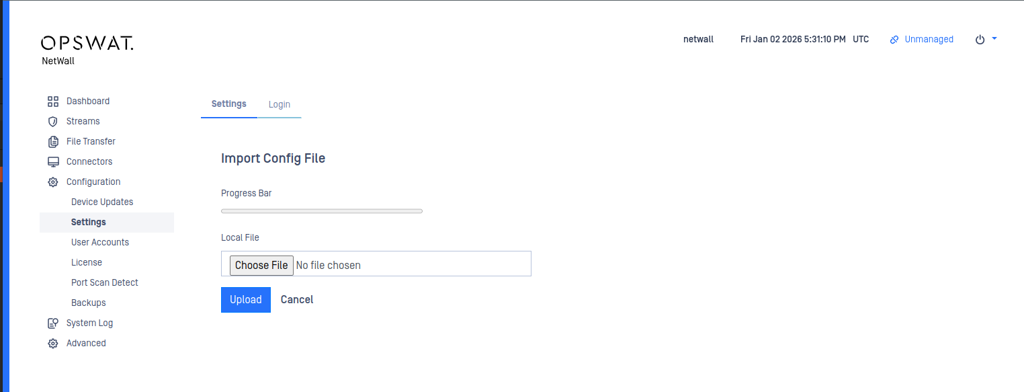
After selecting the Config File button you will see the next screen.
Choose the JSON file and select Upload to import the Jason Configuration File.
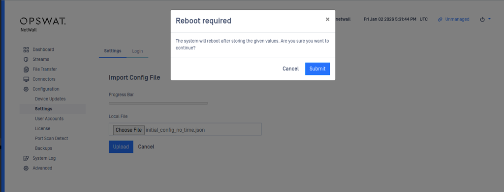
Press Submit and the device will reboot.
Config Configuration File RED
Repeat file upload process on Optical Diode RED.
Proceed with configuring Connectors in the Configuration section.
JSON Configuration File Format
Basic Configuration
TCP Configuration - BLUE
TCP Configuration - RED
UDP Configuration - BLUE
UDP Configuration - RED
HTTP Configuration - BLUE
HTTP Configuration - RED
Syslog Configuration - BLUE
Syslog Configuration - RED