
The Switching section provides Layer 2 network management capabilities for the Industrial Firewall. This section is available in Routing Mode only and is not accessible when the appliance is operating in Transparent Mode.
VLAN Aware-Bridge
A VLAN Aware-Bridge extends a standard network bridge with IEEE 802.1Q VLAN awareness. Each port on the bridge can be configured to accept tagged frames (trunk port), untagged frames (access port), or both, enabling seamless integration with upstream switches and multi-VLAN OT network architectures.
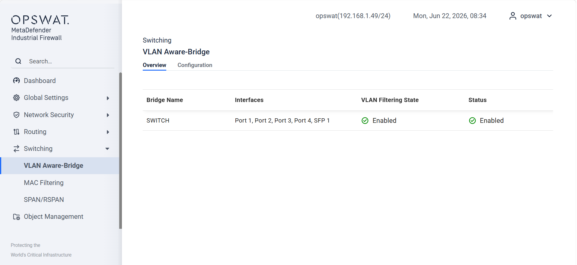
You must enable VLAN Filtering on the bridge for VLAN membership rules to take effect. Without VLAN Filtering enabled, the bridge behaves as a plain Layer 2 bridge and forwards all frames to all ports regardless of their VLAN tag — effectively bypassing all per-VLAN access control configured below.
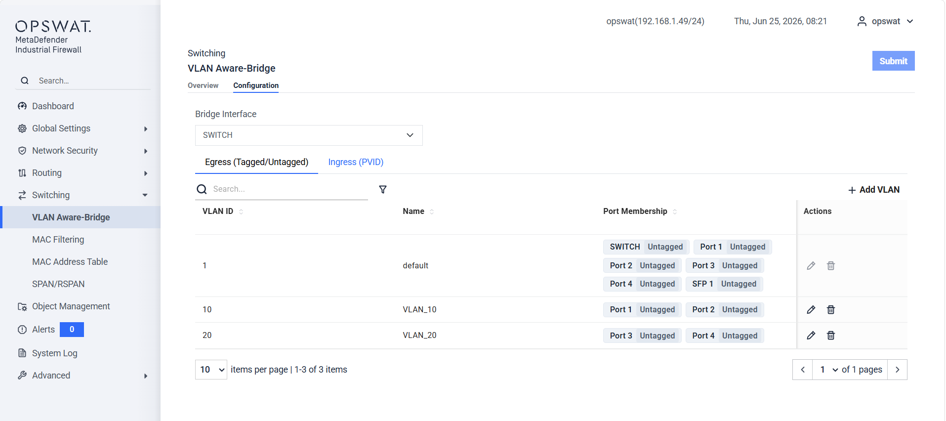
Egress VLAN ID: The VLAN ID that the bridge applies to a packet when sending it out of a port. It determines which VLAN the outgoing frame belongs to on that egress port, and may also control whether the frame is sent tagged or untagged depending on the port's VLAN configuration.
Tagged VLANs: VLANs for which frames are forwarded with the 802.1Q VLAN tag preserved on egress. Use this on trunk ports connected to switches or other VLAN-aware devices.
Untagged VLANs: VLANs for which the 802.1Q tag is stripped before frames are forwarded on egress. Use this on access ports connected to end devices that do not process VLAN tags.
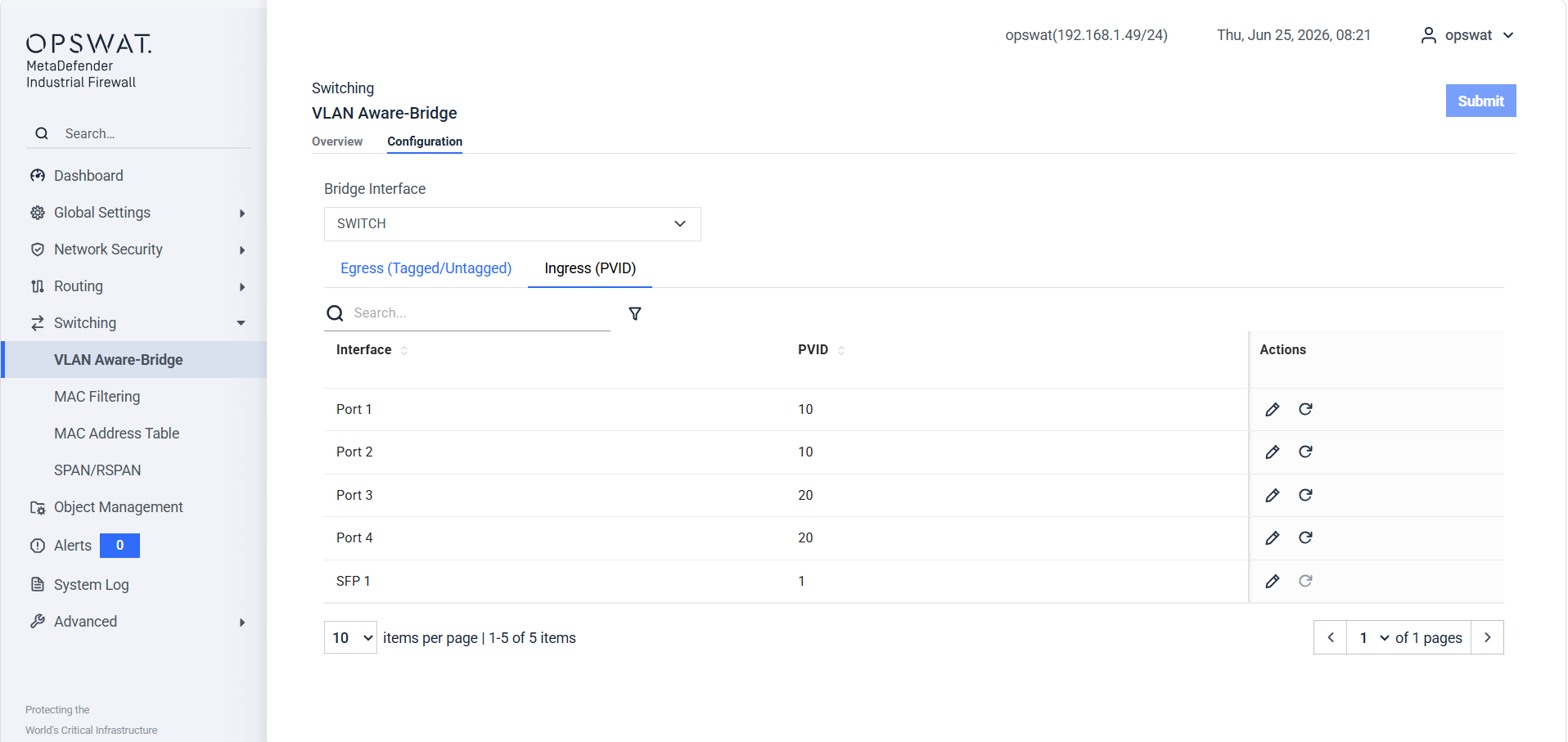
PVID (Port VLAN ID): The default VLAN ID assigned to untagged frames arriving on a port. Frames without an 802.1Q tag are treated as belonging to the PVID VLAN upon ingress.
A port can belong to multiple VLANs simultaneously — as a tagged member for trunk VLANs and as an untagged member for its access VLAN. The PVID must correspond to one of the port's configured VLANs.
MAC Filtering
A security feature that allows or denies network access based on the unique MAC addresses of devices. By creating a list of permitted or blocked MAC addresses, you can control which devices can connect to your network, enhancing security.
Setting
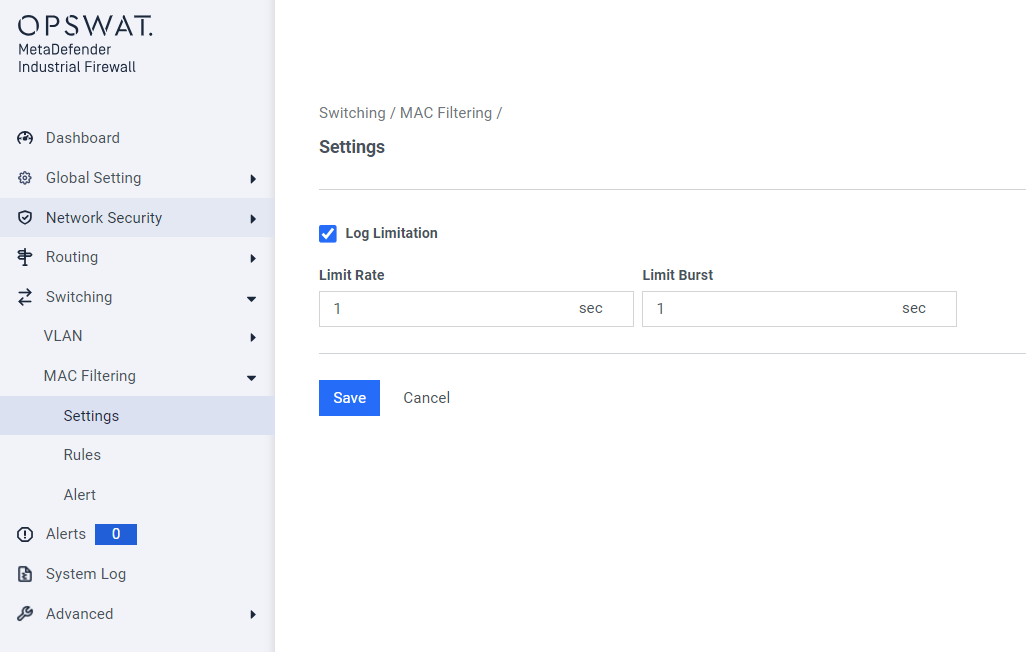
Log Limitation: Restrict the logging of each MAC Filtering rule based on the specified rate limit and burst limit.
Rules
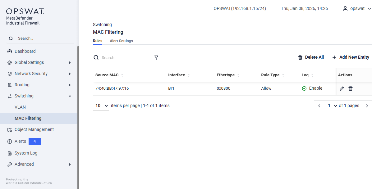
Source MAC: The MAC address of the device initiating the traffic.
Interface: The bridge where the rule is applied. We can create Bridge at Network tab
Destination MAC: The MAC address of the target device.
Ethernet Type: The type of Ethernet protocol being used.
Status: Indicates whether the rule is enabled or disabled.
Log: Option to log traffic that matches the rule.
Action: Options to edit or delete the rule.
Alert
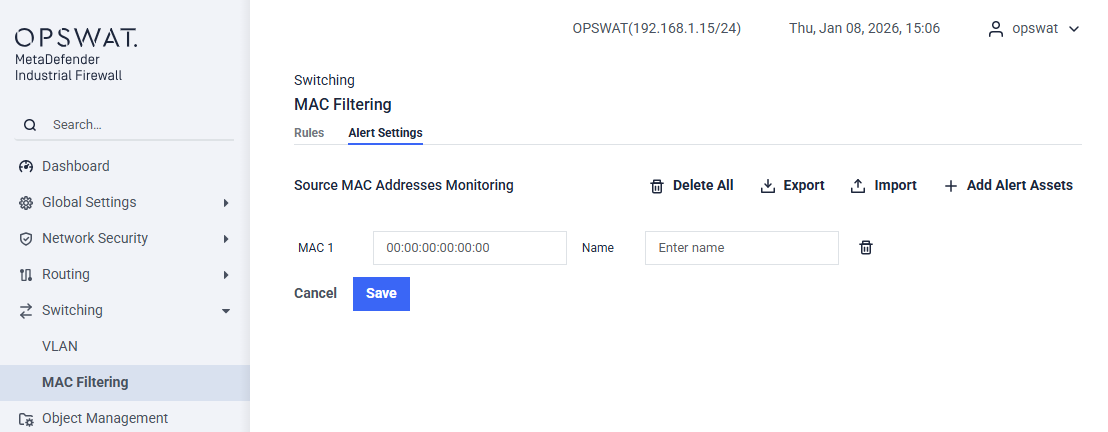
Enter the MAC address in the provided field. Optionally, you can assign a friendly name to the IP or MAC address for easier identification. If you wish to remove the MAC address you just added, click the Delete Last IP/MAC button. The appliance will generate an event for any blocked traffic directed to the MAC address specified on this page.
MAC Address Table
The MAC Address Table displays the live Forwarding Database (FDB) maintained by the Linux kernel bridge. It shows which MAC addresses have been learned on each interface, allowing administrators to monitor device connectivity, identify unknown or unexpected devices on the network, and tune how long learned entries are retained.
Entries Tab
Displays all active MAC address entries currently in the bridge forwarding database.
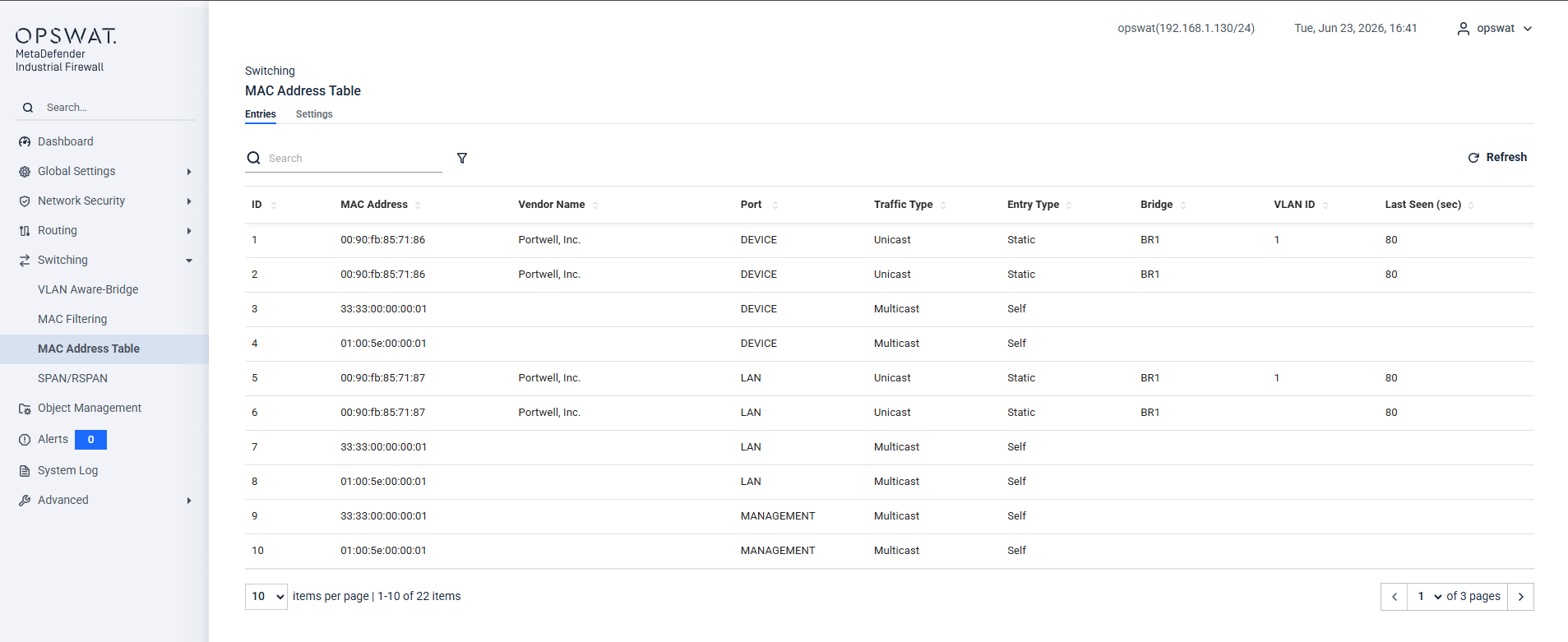
MAC Address: The hardware address of the learned device.
Interface: The physical member interface on which the MAC address was learned (e.g. LAN).
Bridge: The logical bridge the interface belongs to.
VLAN ID: The VLAN associated with this entry. Blank when the bridge does not have VLAN filtering enabled or when the entry is not associated with a specific VLAN.
Entry Type: How the entry was added to the FDB.
Vendor: The device manufacturer resolved from the MAC address OUI prefix. Blank if the OUI is not found in the vendor list.
Settings Tab
Configures how long dynamically learned MAC address entries are retained in the FDB before they expire.
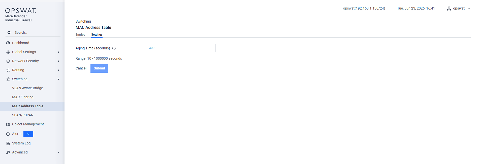
Aging Time: The number of seconds a dynamically learned entry remains in the table without being refreshed by new traffic. When a device stops sending frames, its entry is removed after this period. Valid range: 10–1,000,000 seconds. Default: 300 seconds.
SPAN/RSPAN
SPAN copies traffic from selected source ports to a destination port so it can be inspected by a monitoring device without affecting the original traffic. Sessions are supported in both Routing Mode and Transparent Mode, including on an appliance running both at once. Mirroring is configured the same way in either case, and a single session can mirror routing ports and transparent pairs together.
Routing Mode: Each port assigned to routing can be mirrored individually, with the direction set to Ingress, Egress, or Both.
Transparent Mode: Each configured pair is offered as a single source entry, for example Bridge1 (LAN1 ↔ LAN2), and captures every frame crossing the pair in both directions. The inline path is not broken while mirroring is active, and Both (Ingress + Egress) is the only direction available for a pair.
SPAN
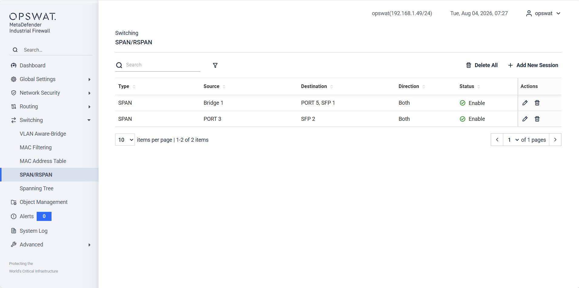
Source Port(s): One or more interfaces whose traffic is mirrored.
Direction: Controls which traffic direction is mirrored: Ingress (Rx): Mirror only inbound traffic on the source port Egress (Tx): Mirror only outbound traffic on the source port. Both: Mirror all traffic in both directions (default).
Destination Port[s]: One or more interfaces where mirrored traffic is delivered. Connect to a monitoring device such as an IDS sensor, packet analyzer, or data recorder. The destination port only receives mirrored frames and cannot forward normal network traffic while assigned to a SPAN session.
RSPAN
RSPAN uses a dedicated VLAN to transport mirrored traffic across multiple switches to a remote destination. The source switch encapsulates copied frames in the RSPAN VLAN; the destination switch strips the RSPAN encapsulation and delivers the frames to the monitoring port.
RSPAN is configured in two roles — each role is set up separately on the respective appliance:
RSPAN - Source Switch
Configured on the appliance where the traffic to be monitored originates. The source switch captures frames from the specified source ports and floods them into the RSPAN VLAN, which carries the mirrored traffic toward the destination switch over trunk links.
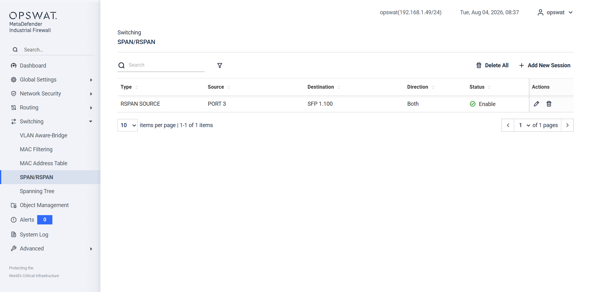
RSPAN VLAN: The dedicated VLAN ID used exclusively to carry mirrored traffic between the source and the remote destination. This VLAN must be configured as a trunk VLAN on all intermediate switches in the path. Do not use this VLAN for any production traffic.
RSPAN - Destination Switch
Configured on the appliance where the monitoring device is connected. The destination switch receives mirrored frames from the RSPAN VLAN, strips the RSPAN encapsulation, and forwards the reconstructed frames out of the designated destination port to the monitoring device.
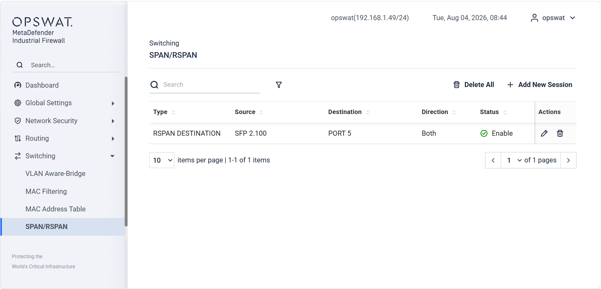
RSPAN VLAN: The dedicated VLAN ID used exclusively to carry mirrored traffic between the source and the remote destination. This VLAN must be configured as a trunk VLAN on all intermediate switches in the path. Do not use this VLAN for any production traffic.
Spanning Tree Protocol
Spanning Tree Protocol (STP) is a Layer 2 network protocol used to prevent switching loops in Ethernet networks. It allows redundant network paths to remain available while logically blocking unnecessary paths to ensure that only one active path exists between network segments.
By preventing Layer 2 loops, STP protects the network from problems such as broadcast storms, duplicate frames, and MAC address-table instability. STP is commonly used in switched Ethernet networks where redundant links are required for reliability.
Global
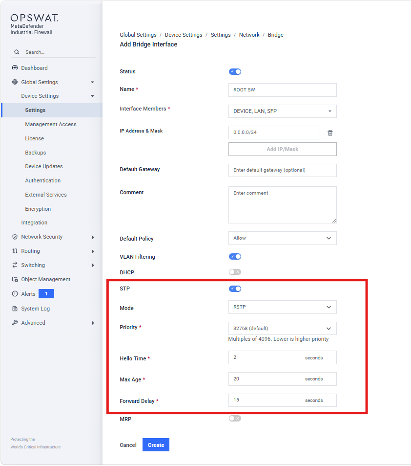
Priority: The bridge priority and its own MAC address make up this separate Bridge ID. The device with the best (numerically lowest) priority assumes the role of the root bridge. Define the root device by assigning the device the best priority in the Bridge ID among all the devices in the network. Enter the value as a multiple of 4096.
Hello Time: The local Hello Time is the time in seconds between the sending of two configuration messages (Hello packets).
Max Age: In STP protocol, the Max Age parameter was used to specify the validity of STP BPDUs in seconds. For RSTP, Max Age signifies the maximum permissible branch length (number of devices to the root bridge).
Forward Delay: In STP protocol, the Forward Delay parameter was used to delay the status change between the statuses: disabled, discarding, learning, forwarding. Since the introduction of RSTP, this parameter has a subordinate role, because the RSTP bridges negotiate the status change without any specified delay.
Port
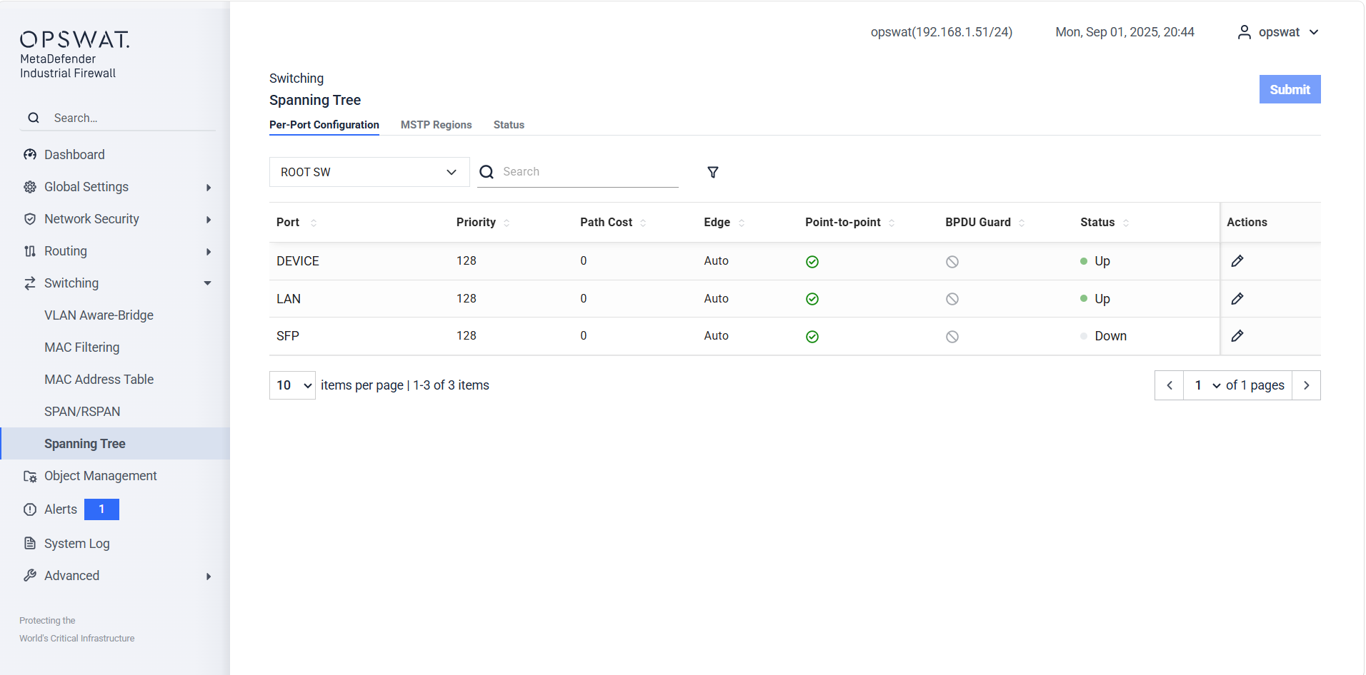
Priority: Port priority used when STP selects the preferred path. A lower value has higher priority.
Path Cost : The cost associated with using the port as part of the spanning-tree path. A lower cost is preferred. Set to 0 for automatic cost
Edge: Determines whether the port is treated as an edge port. Edge ports normally connect to end devices rather than other switches.
Point-to-point: Indicates whether the port is operating as a point-to-point link.
BPDU Guard: Protects an edge port by disabling or blocking it when a BPDU is received.
Status: Displays whether the physical interface is currently Up or Down.

Role: STP role assigned to the port, such as Designated, Root, Alternate, or Disabled.
Stale: Current forwarding state of the port.
Path Cost: STP path cost associated with the port.
Priority: Port priority used when selecting the spanning-tree path.
Media Redundancy Protocol (MRP)
Media Redundancy Protocol (MRP) is used to provide network redundancy in an industrial Ethernet ring topology. MRP helps prevent network interruptions by detecting a link failure and switching communication to the alternate path in the ring.
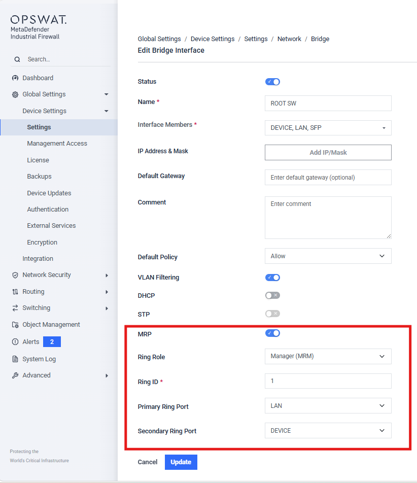
Ring Role: The role of the device in the MRP ring: Manager (MRM) – The device manages the MRP ring and monitors the ring status. Client (MRC) – The device participates in the MRP ring as a client.
Ring ID: ID to distinguish the ring from other MRP rings in the network.
Primary Ring Port: The first network interface that will participate in the MRP ring.
This port must be physically connected to one side of the ring.
Secondary Ring Port: The second network interface that will participate in the MRP ring.
This port must be physically connected to the other side of the ring.
The Primary Ring Port and Secondary Ring Port should be two different physical interfaces.